1936 Ford Five Window Coupe Street Rod Restoration 2018
January
Air Conditioning Duck Fabrication and Installation
The former owner of this car had air conditioning installed,
however the air flow would only come out of three hoses hanging straight down from
under the dash.
The problem was our feet would freeze, and the rest of
us would be uncomfortably warm on a hot day. The reason for this problem was the
thermostat was also located under the dash, and it would keep turning the air off before
completely cooling the cabin. I was stuck between a rock and a hard place, I did not want to change
the look of the mostly stock Dash however I needed to divert the air flow to the
passengers inside the cabin to more efficiently control the temperature.
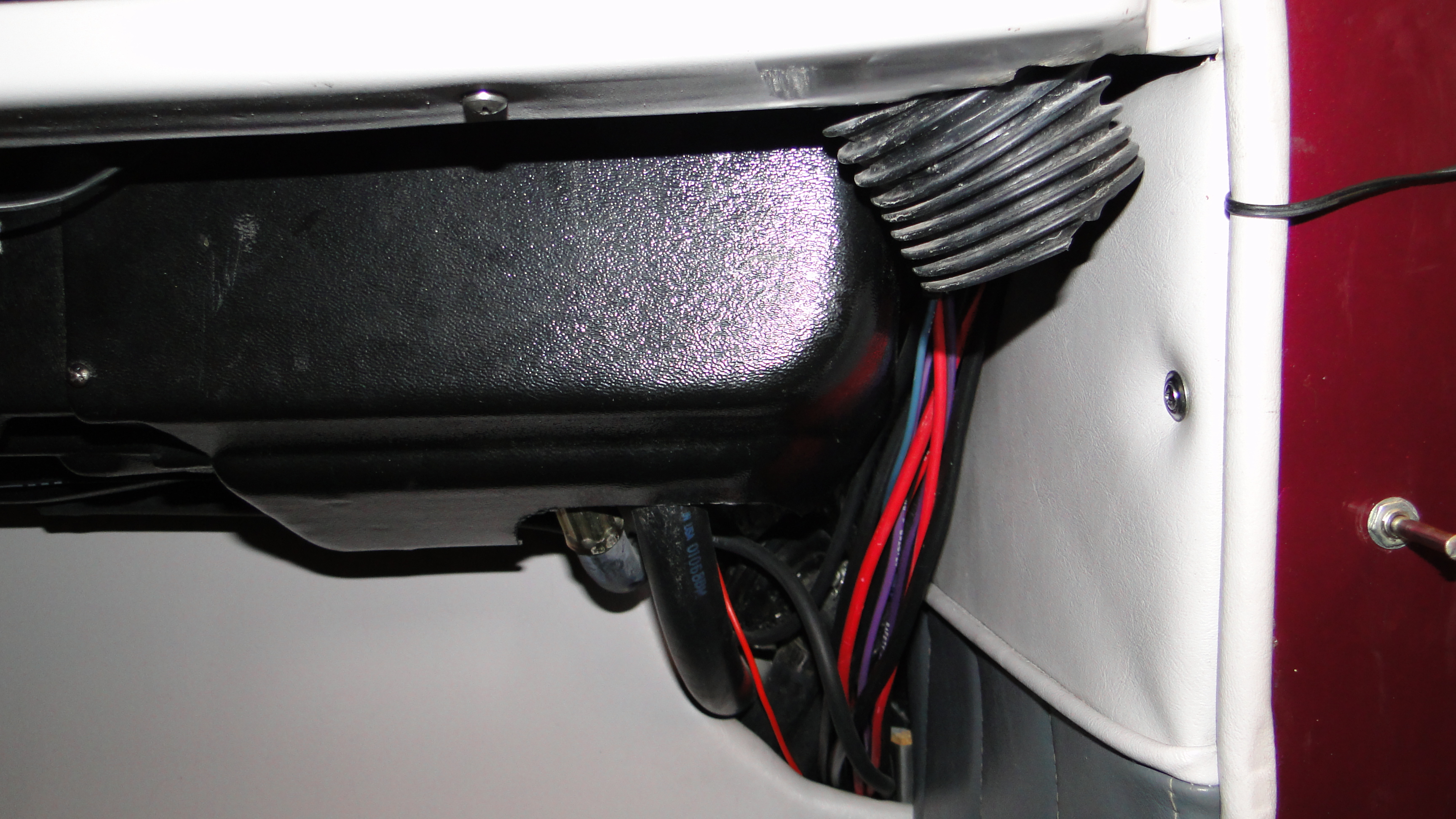
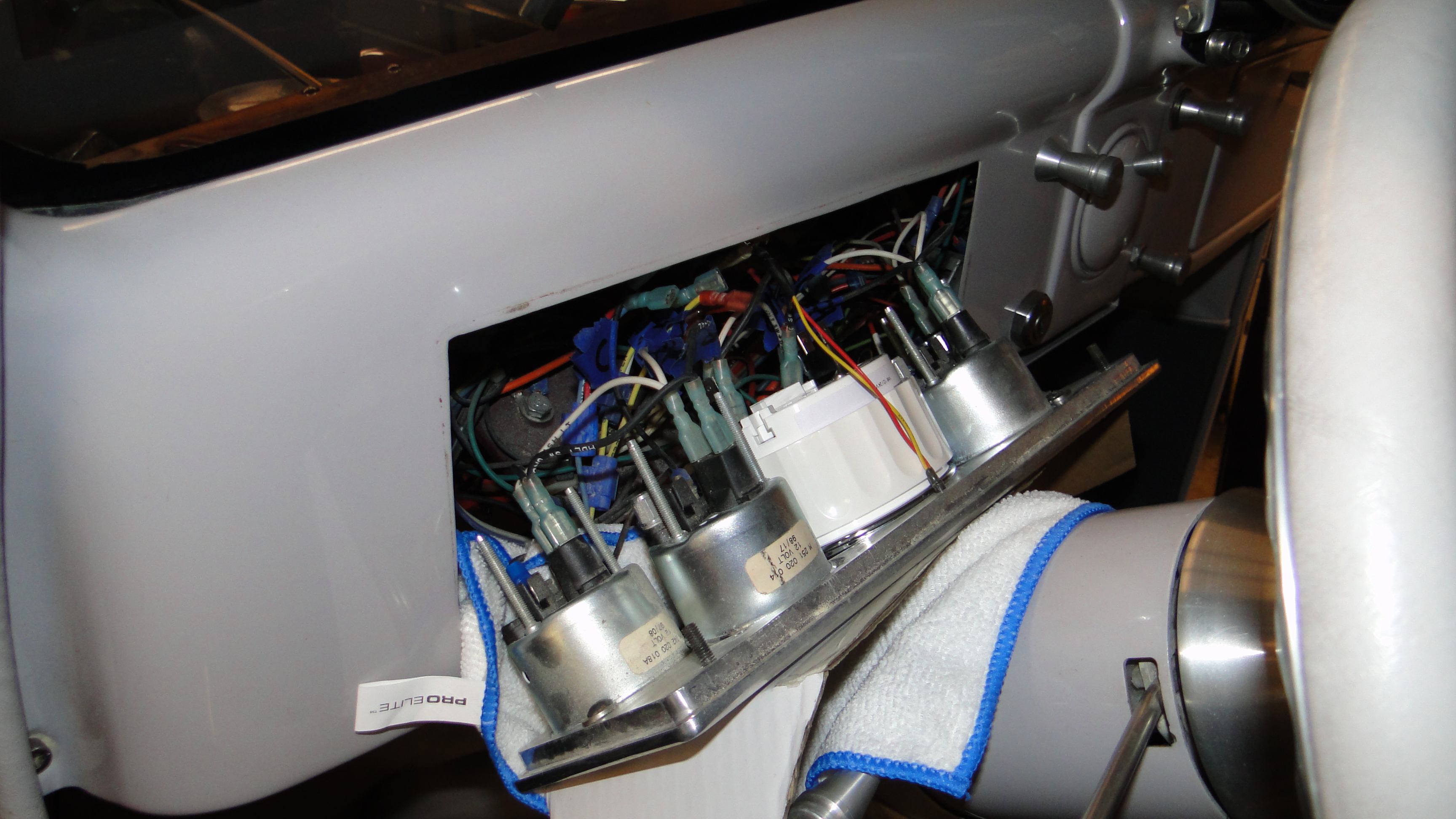
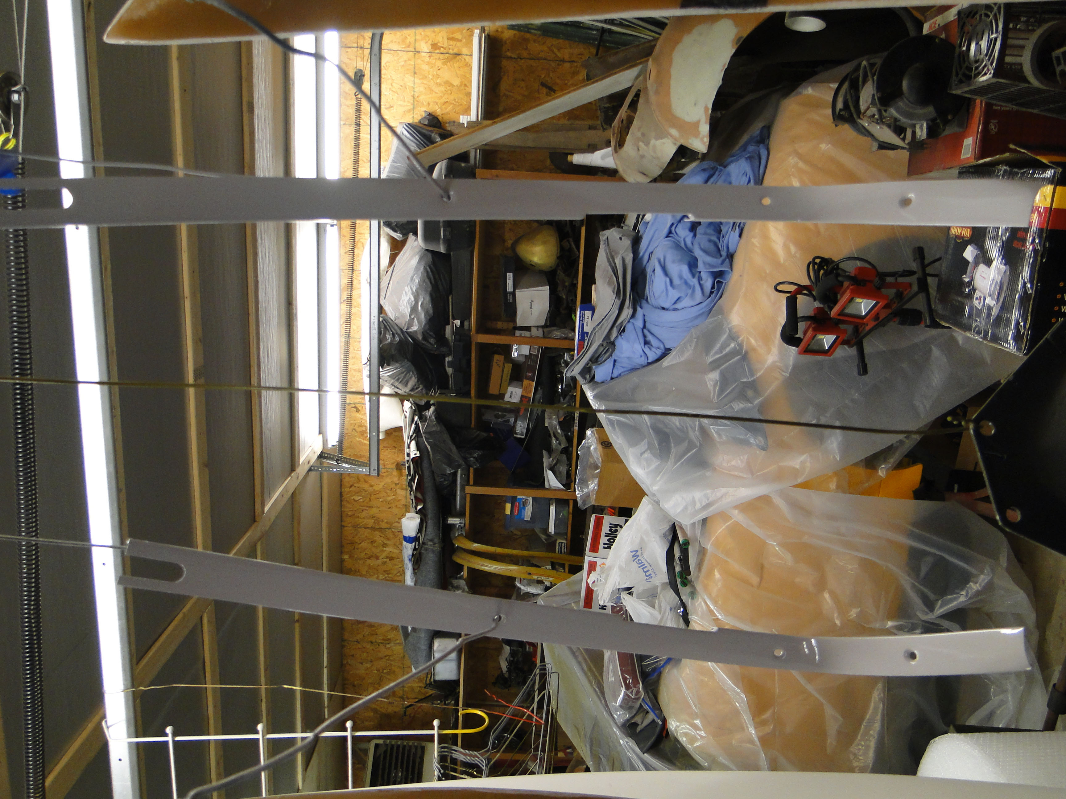
My idea was to somehow conceal the air tunnels under the dash. As
you can see from the photo there was very little room, and a lot of devices that
needed to be worked around.
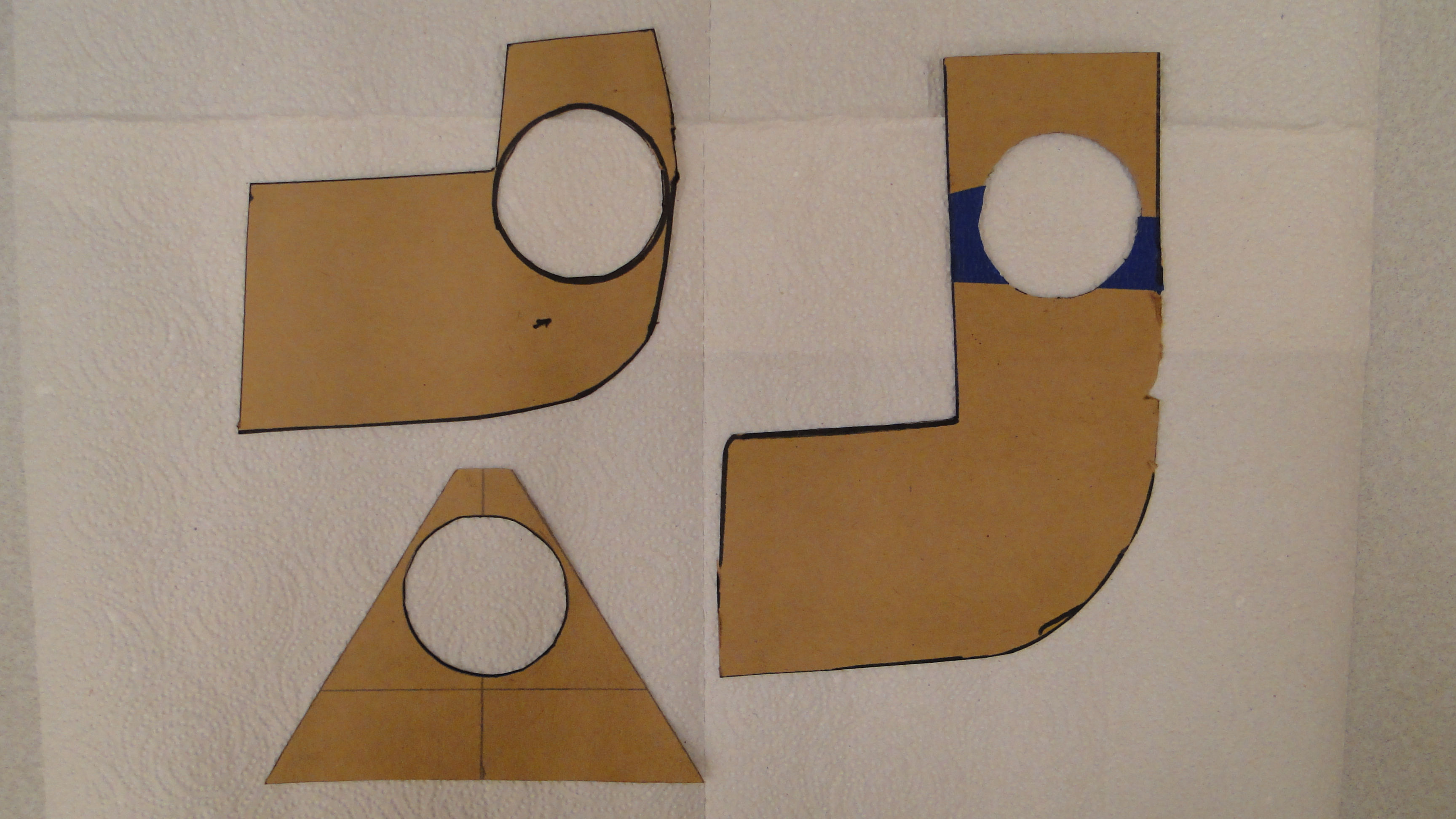
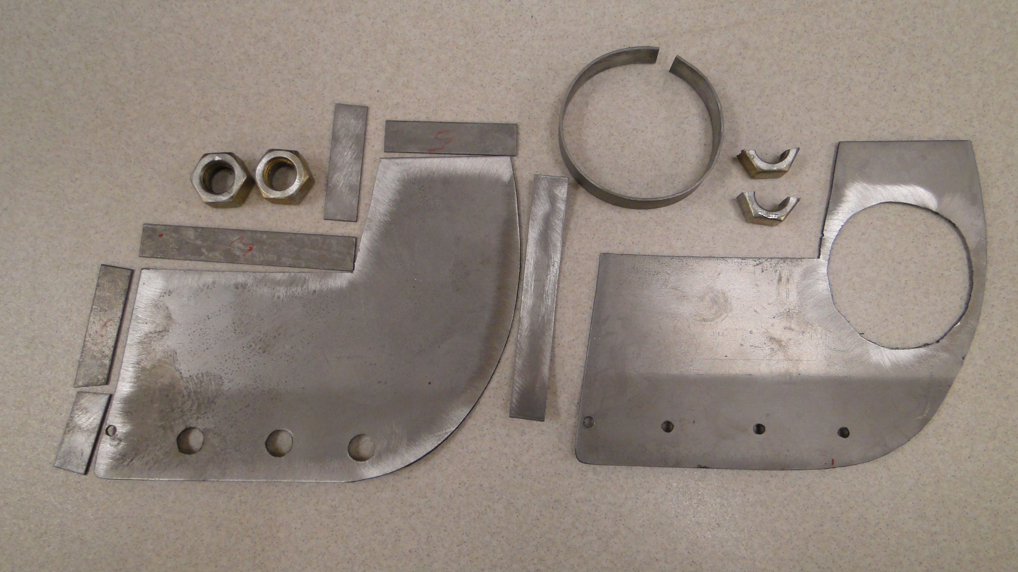
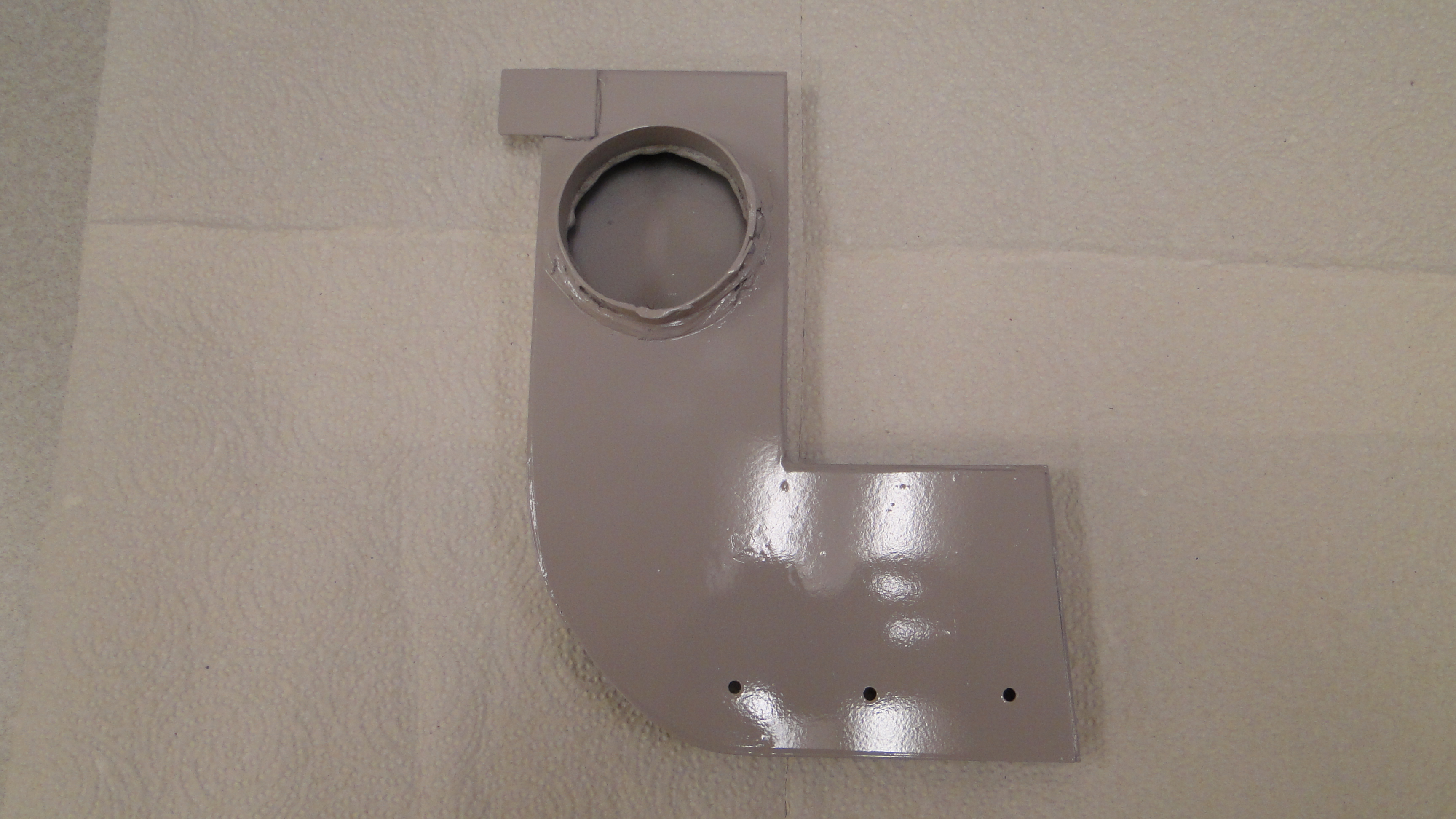
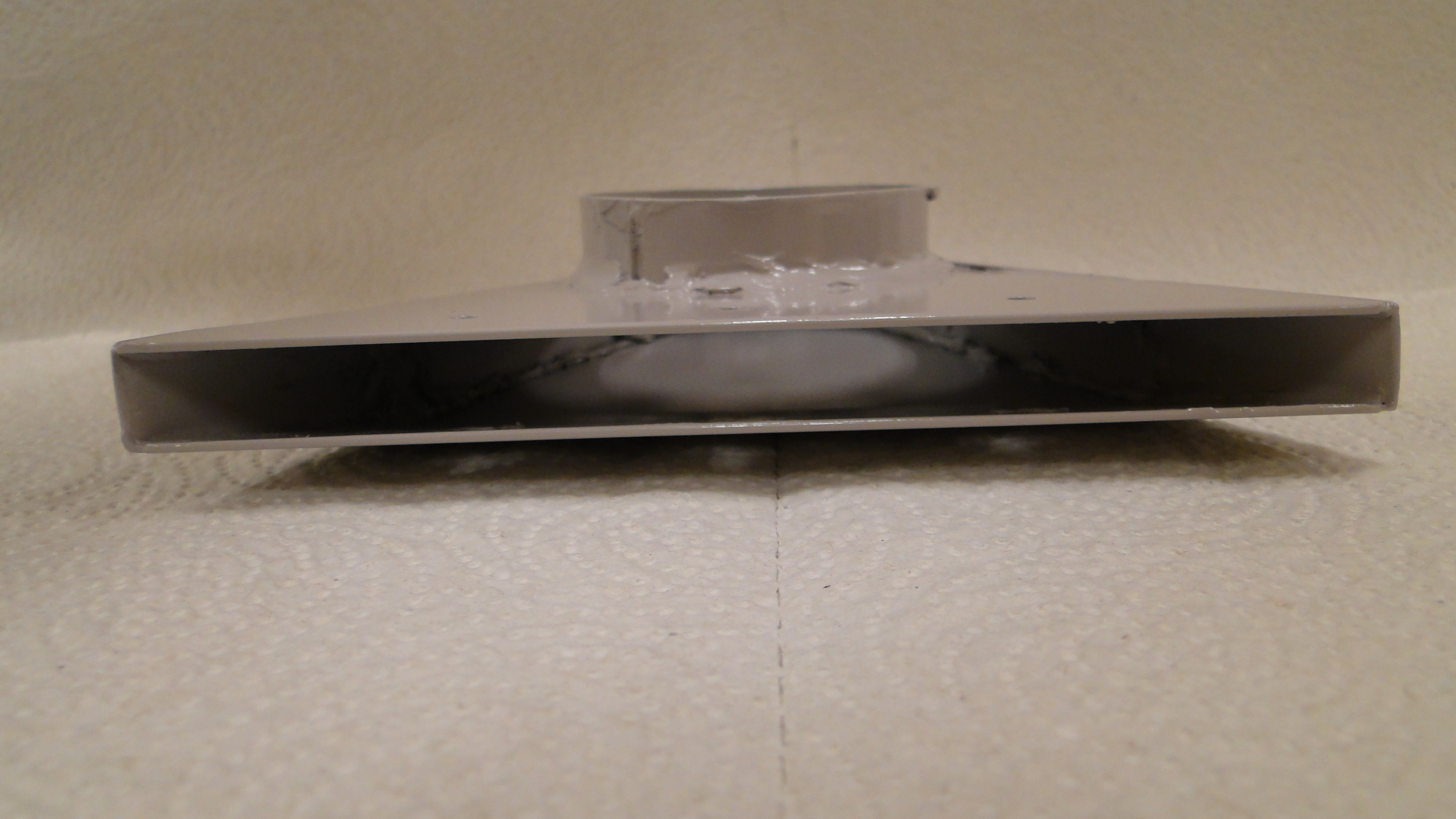
First I had to cut a cardboard template for a test fit,
under the Dash where the air hoses were hanging down. Next I needed
to cut the metal to match my cardboard templates. Then I used large
nuts for the air tunnel spacing. Each of the three vent tunnels were
completely different, which made fabricating them very time consuming.
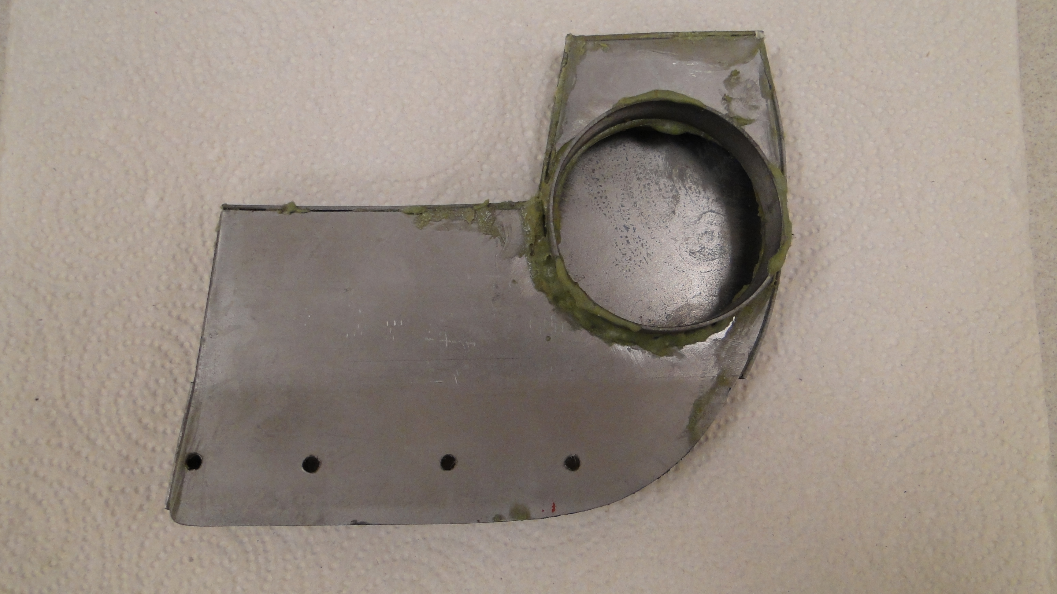
Then I had to choose between welding or gluing the metal vent tunnels together,
I went with Fuser adhesive for this project. After the glue dried, I
grounded off the ruff edges and
excess glue.
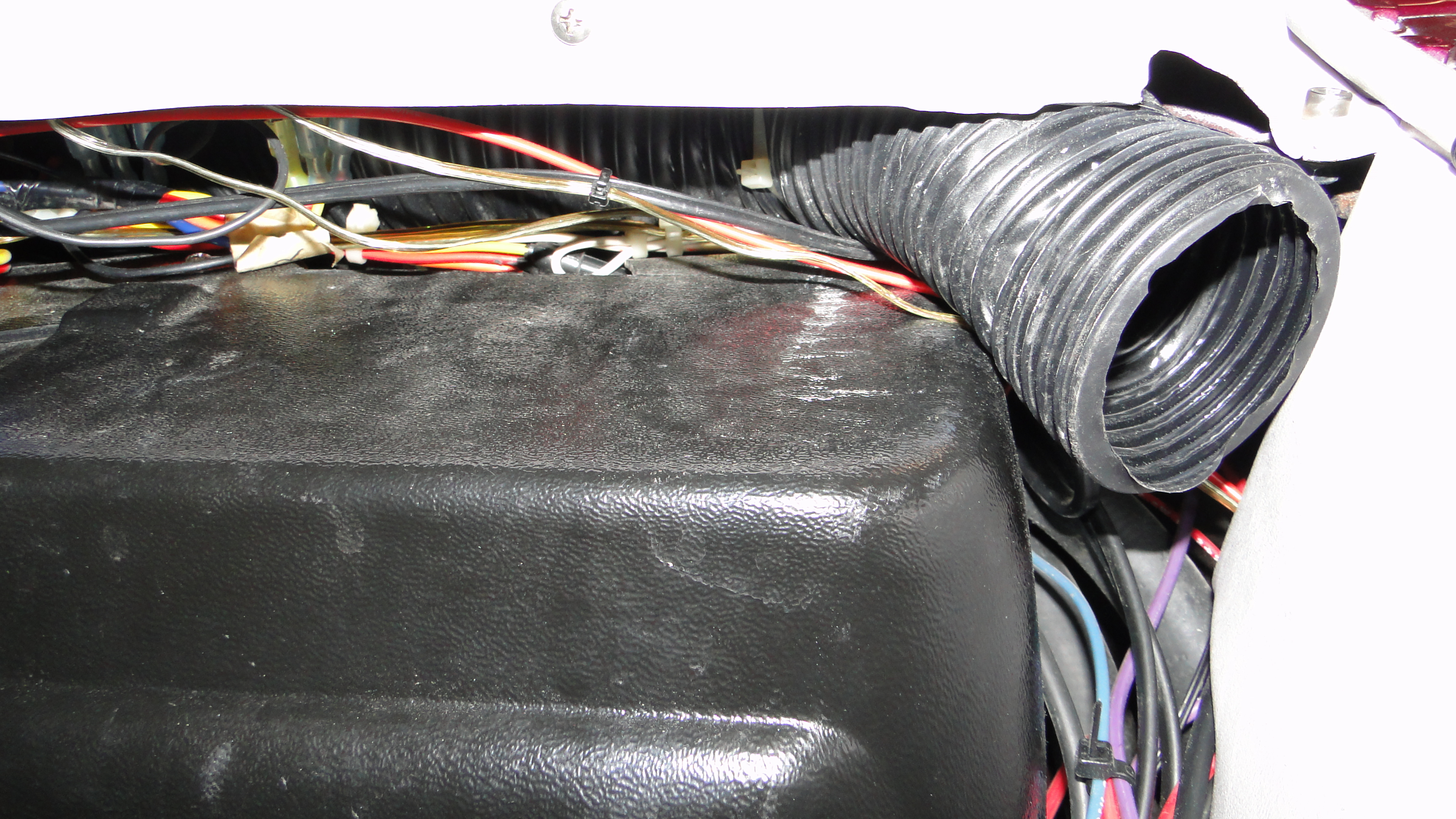
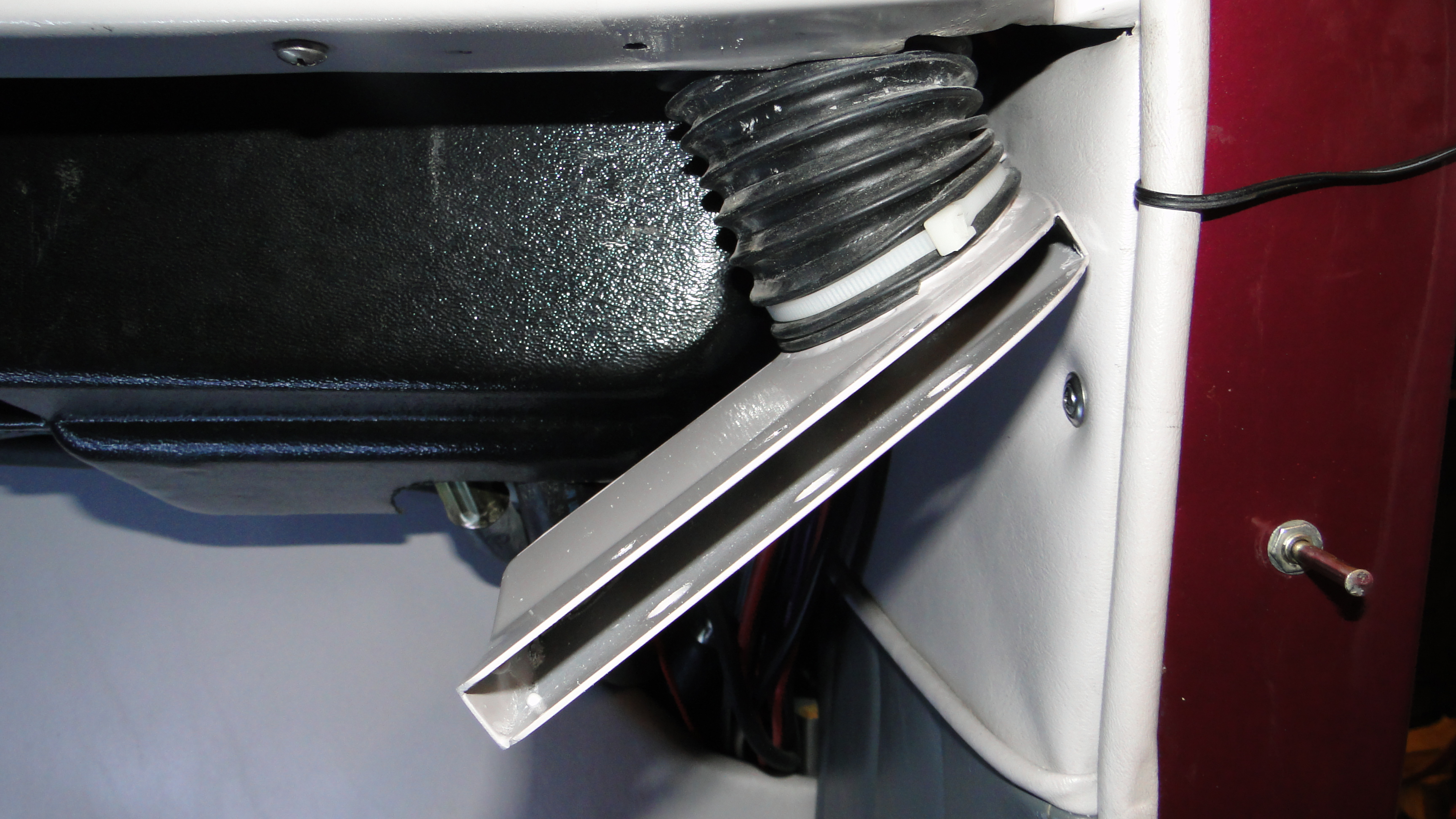
I had to use wire ties over the hoses to secure them to the tunnels hose
gateways, then
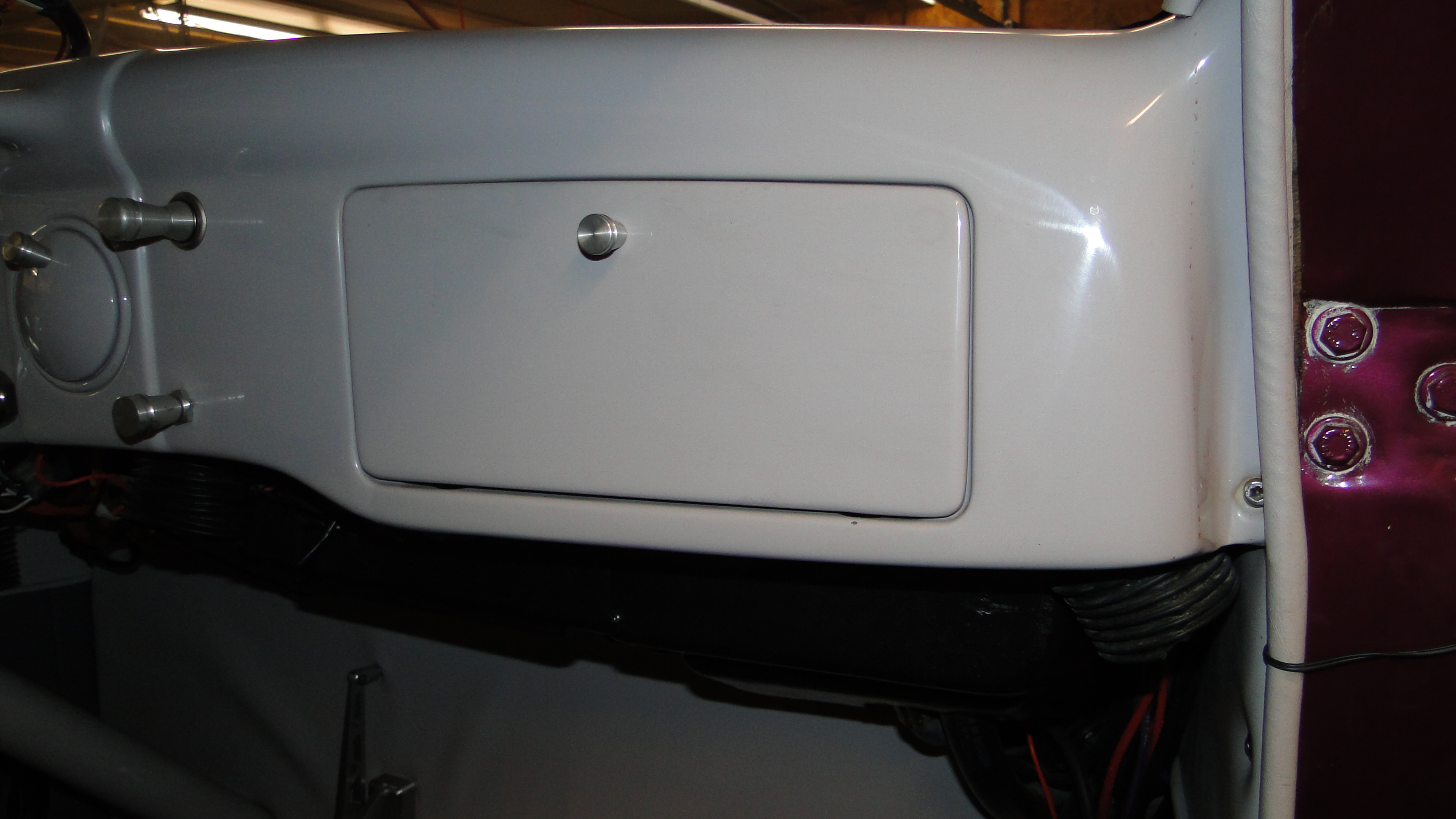
screw the tunnels on to the bottom of the dash. Last but not least I
covered my access holes with rubber caps for that professional finish. Look closely you can hardly see
the vents under the Dash.
VDO Digital Speedometer Problems
For the past five years ever since I purchased this
car, the speedometer never worked. In the past it just never seem to
be a priority for me, however last year I started to finish the car mechanically.
In the summer I
tried to configure it, resetting it, and nothing seemed to work as advertised.
I have said this before and I will say it again, nothing
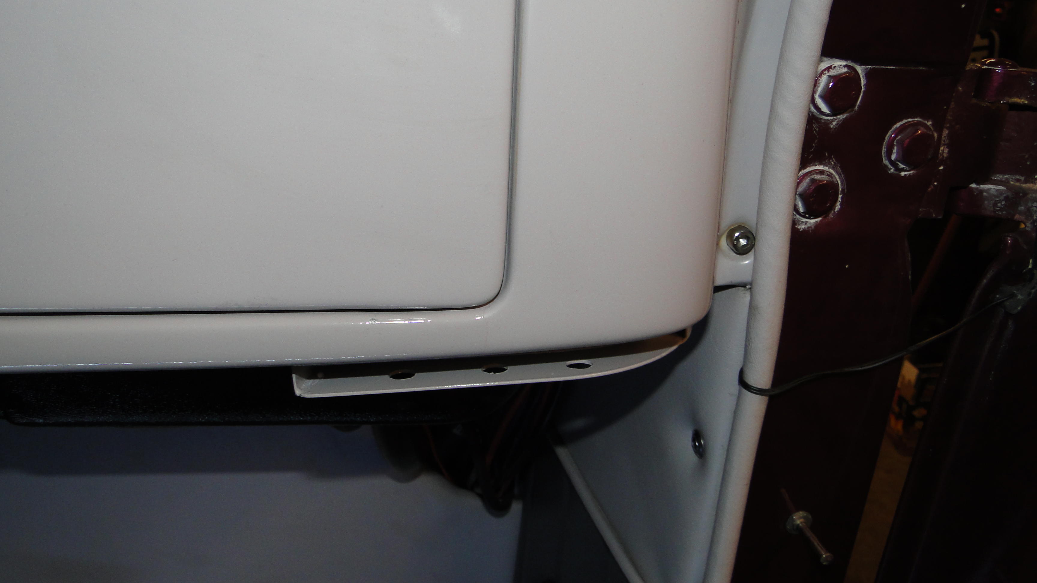
is easy with this car. To remove the speedometer I had to first
remove the dash plate that it was attached to, this is normally no big deal. However the
dash plate was bolted on the dash from the rear and getting though the wiring proved
to be very difficult. With a extendable two inch mirror in one hand to see
the dash plate nuts, and my air wrench in the other I was able to finally remove
the dash plate. For those of you
that don't realize how difficult this is to do, remember when your working with
a mirror everything is opposite to move left you have to move right and up is
down and so on.
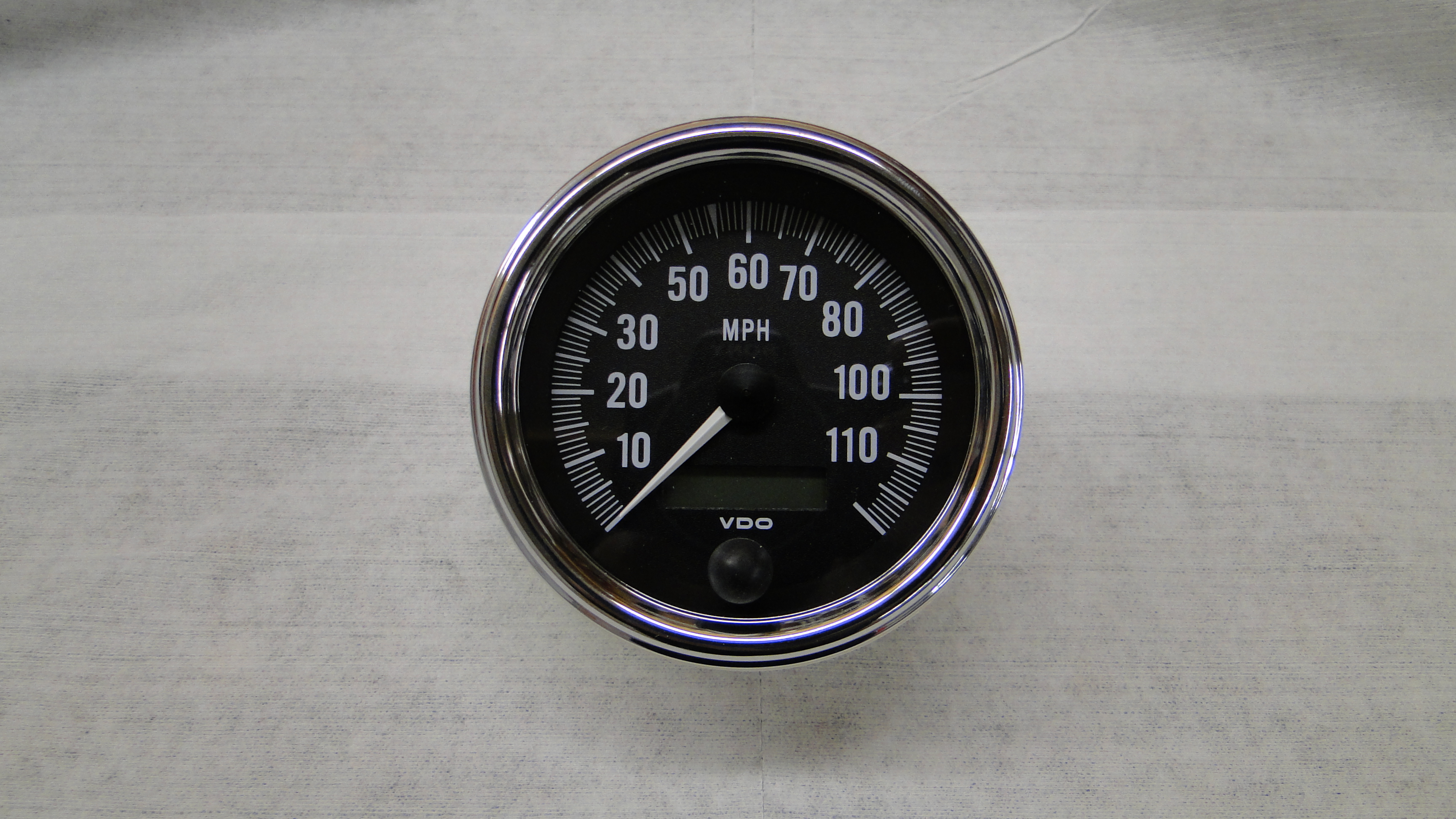
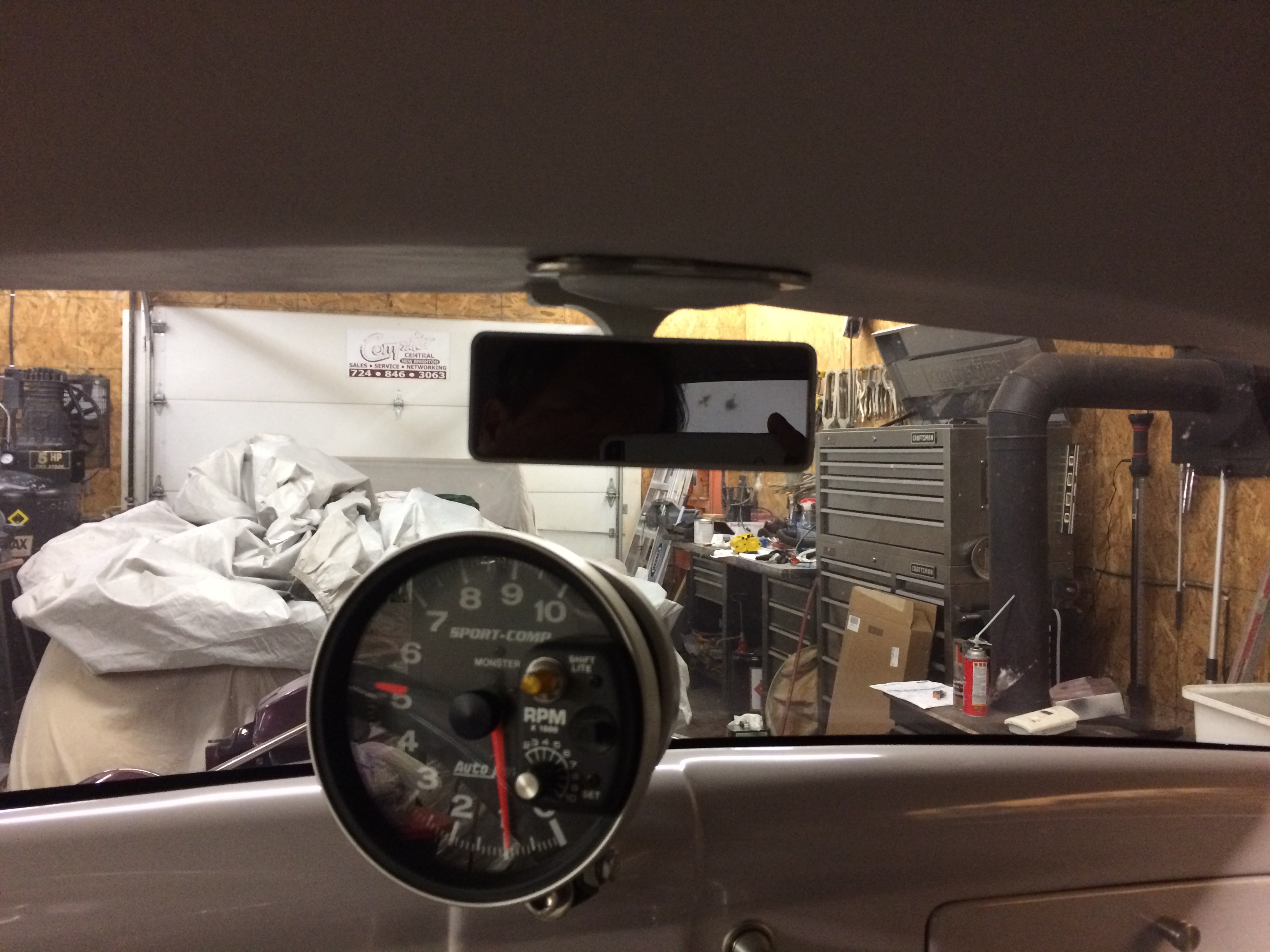
Once the speedometer was removed I called the very nice people at VDO and they
recommended Paul at Lauderdale Speedometer and Compass out of Florida for
the service work. I sent Paul my Speedometer and they tried to test it. See
first photo.
To their surprise my unit was completely dead they could not retrieve any
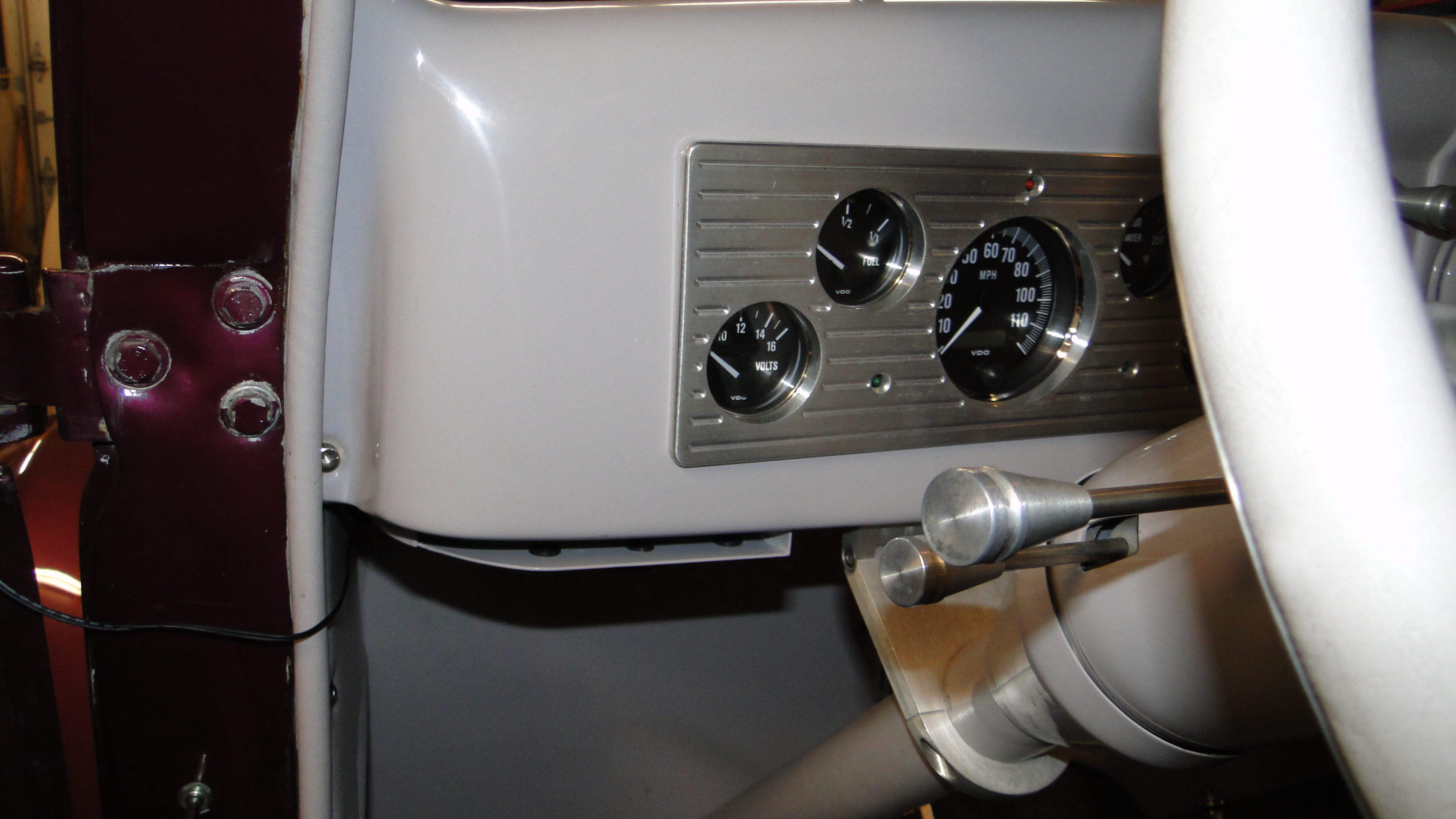
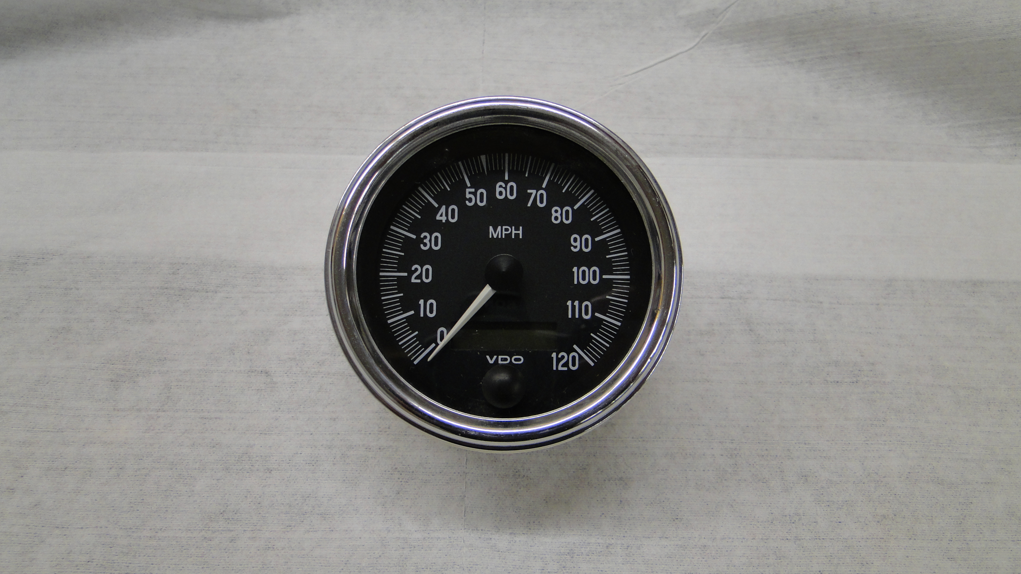
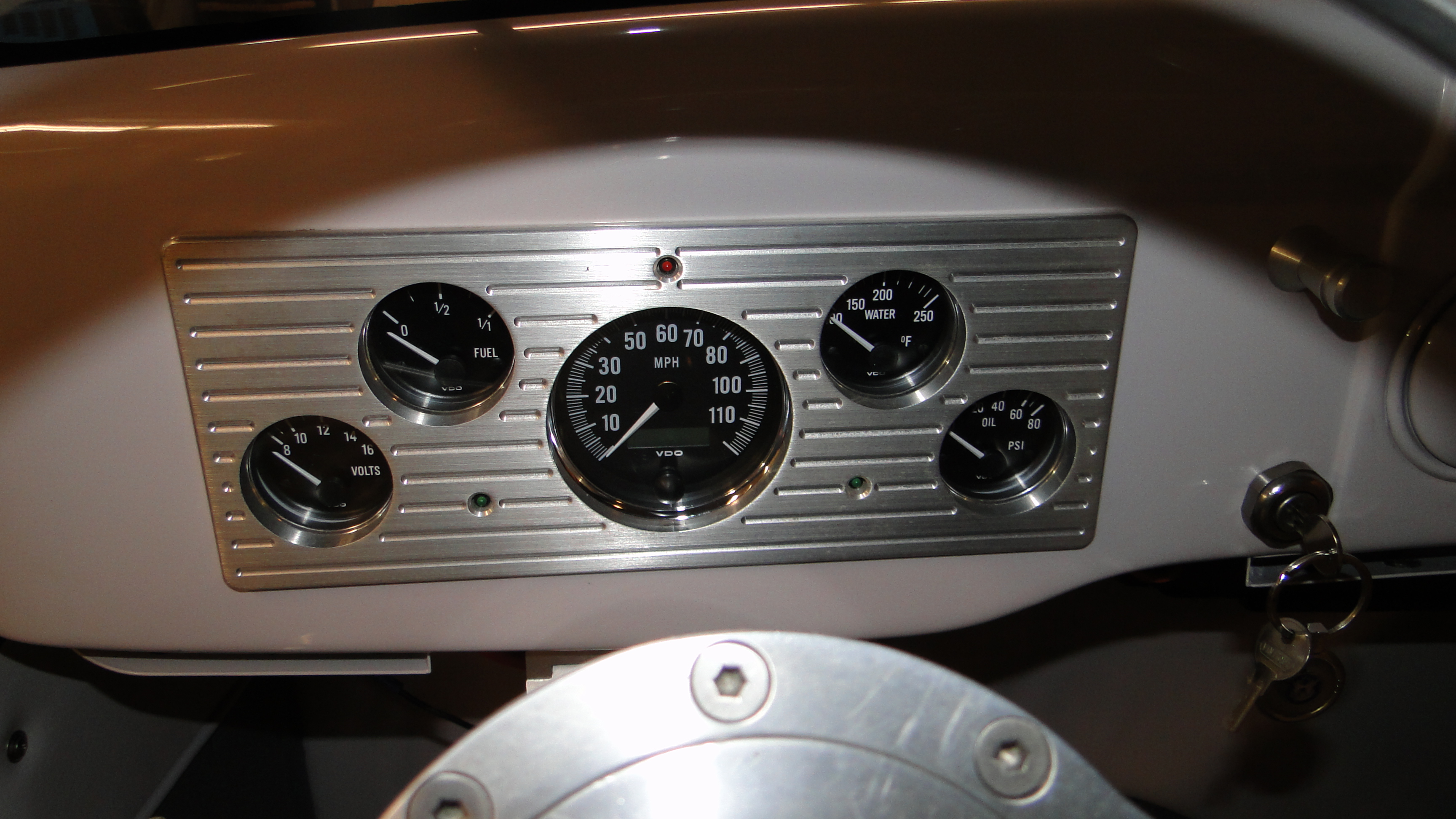
configuration or mileage data from it. Paul then sold me a brand new
speedometer that kind of matched the faces of my other devices, and could connect to my
existing wiring for a reasonable price. See second photo.
The unit was not an exact a match however it looks good
and we will see if it works this spring.
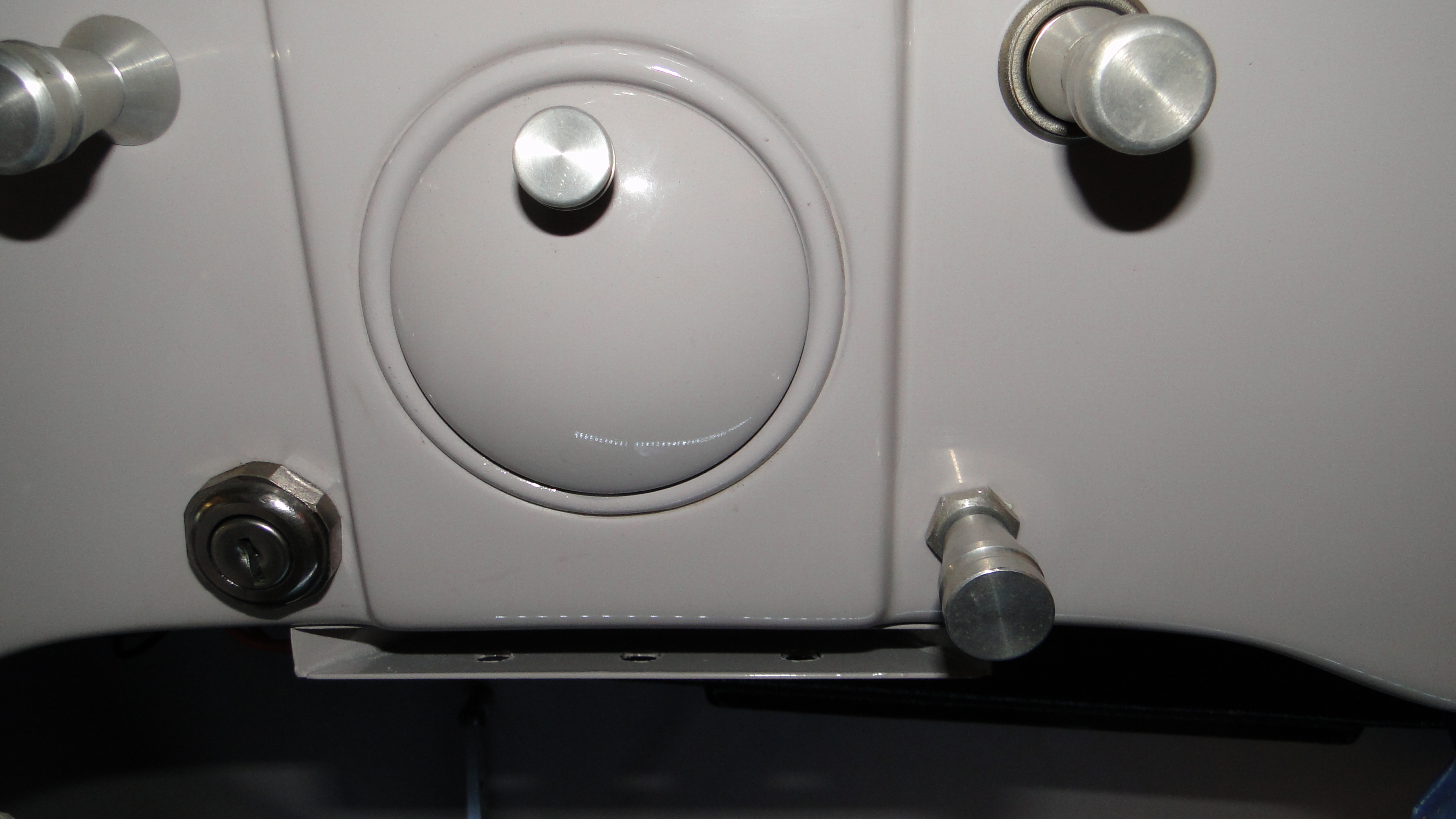
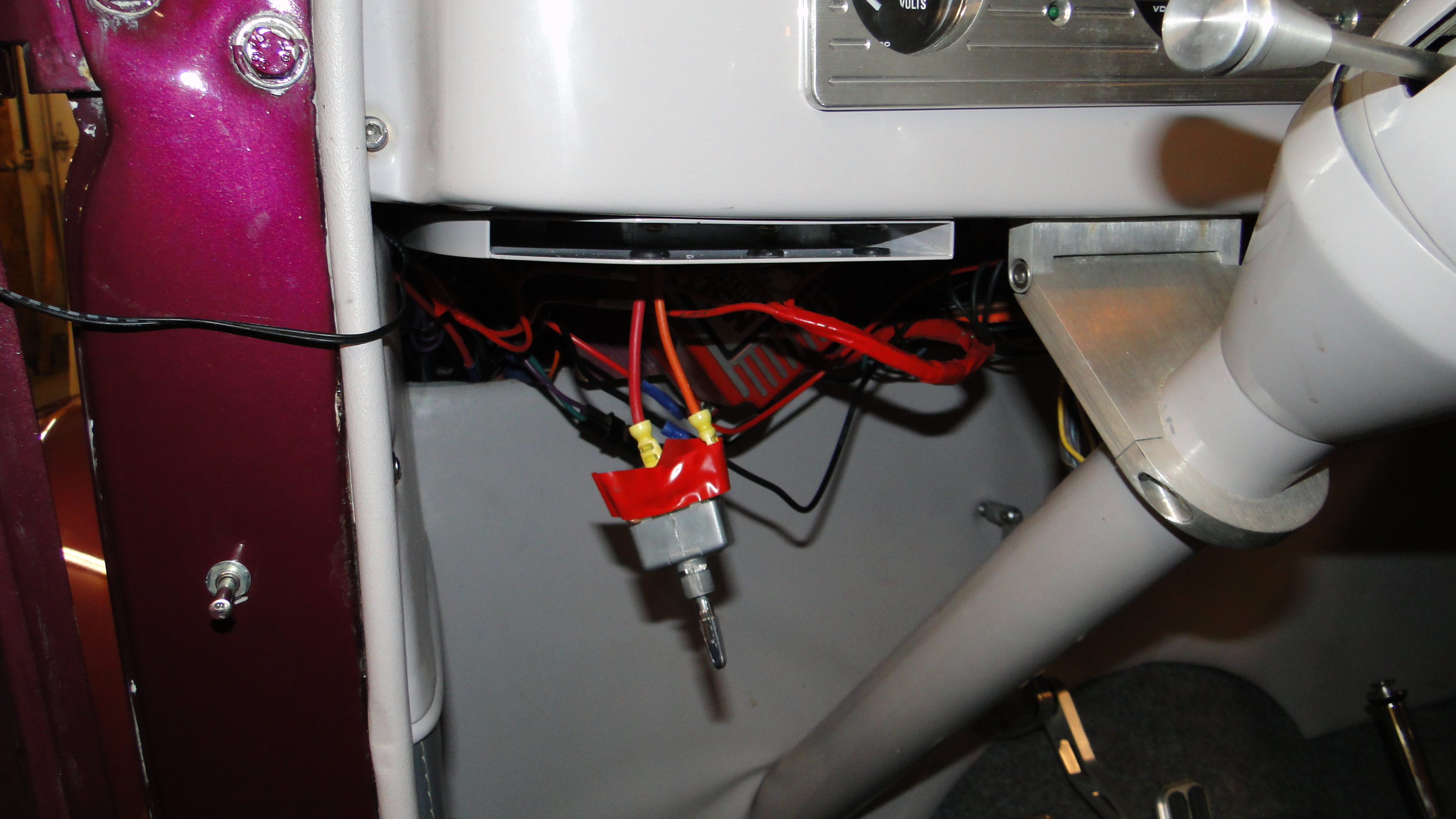
Mystery Switch
When I was working on the speedometer installation, I
found a three way switch buried in the dash that only had two wires connected to
it. At first I thought it was a hidden kill switch, however after
testing it with my volt meter, I found that the switch was currently in the off
position. I traced one end of the wire to the ignition
switch, and the other end routed to where a electric radiator fan would need
powered. It would seem at some point in the past an electric fan was, or was
going to be installed on this car.
Click any picture to enlarge.
Click picture to enlarge.
Click any picture to enlarge.
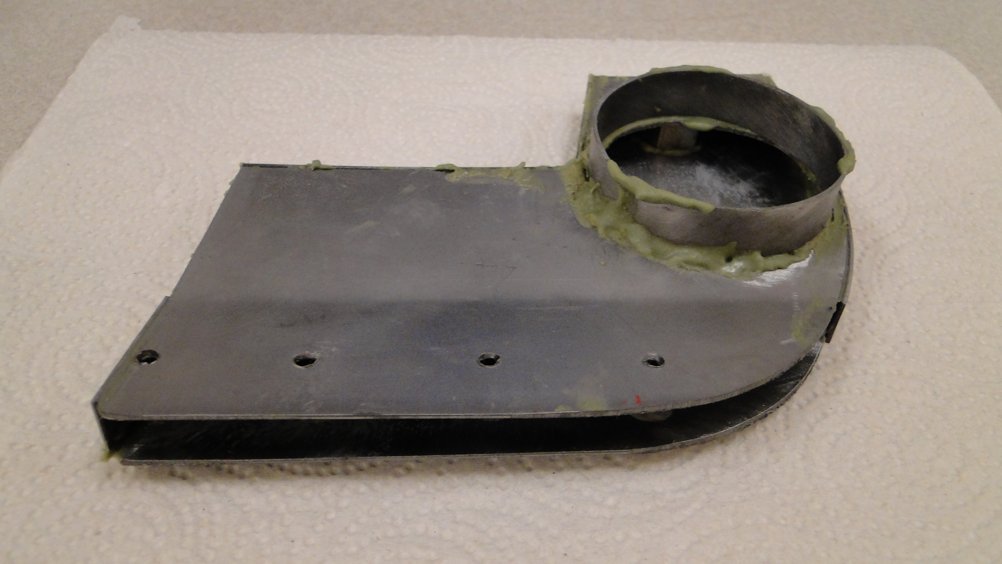
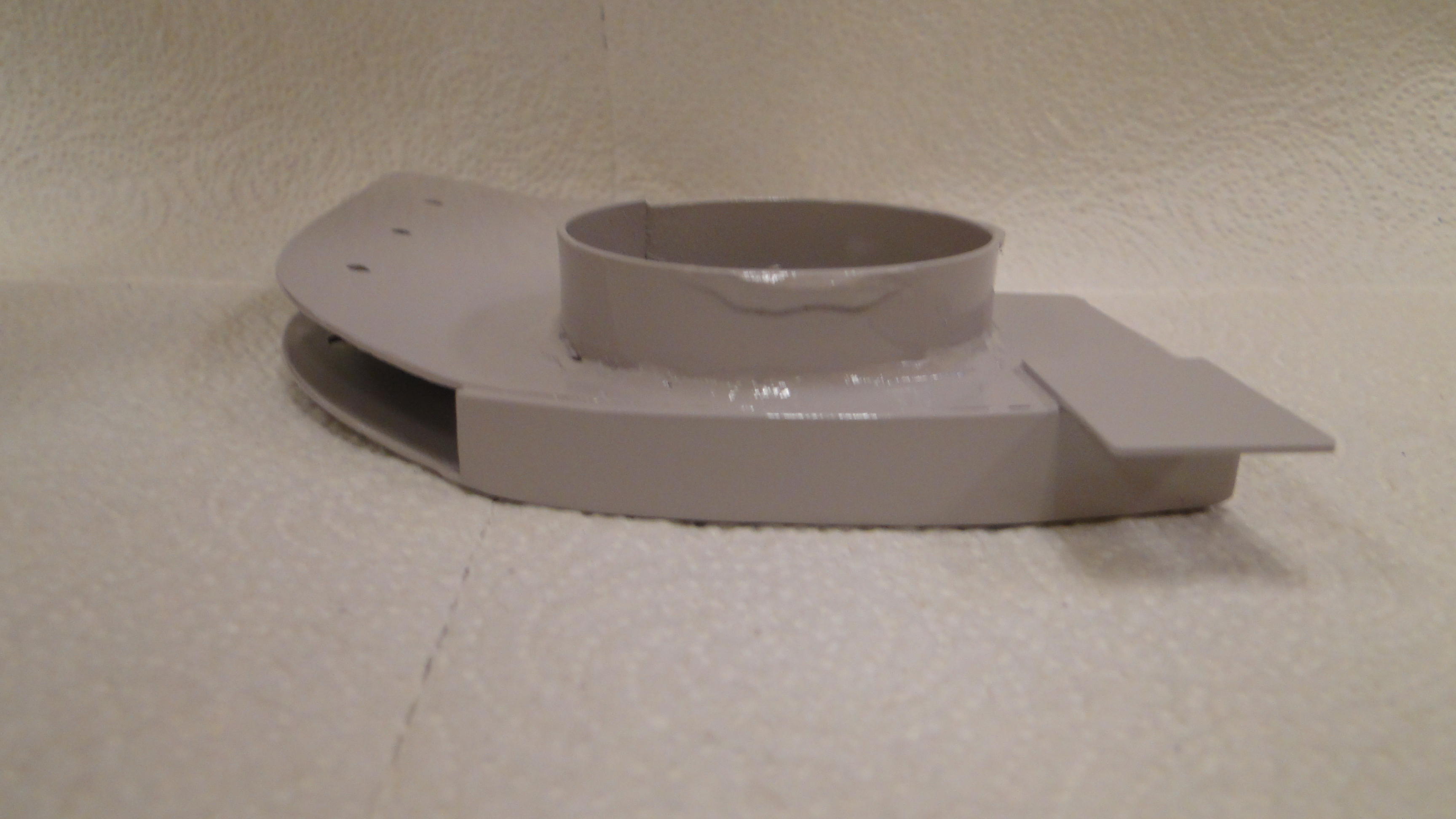
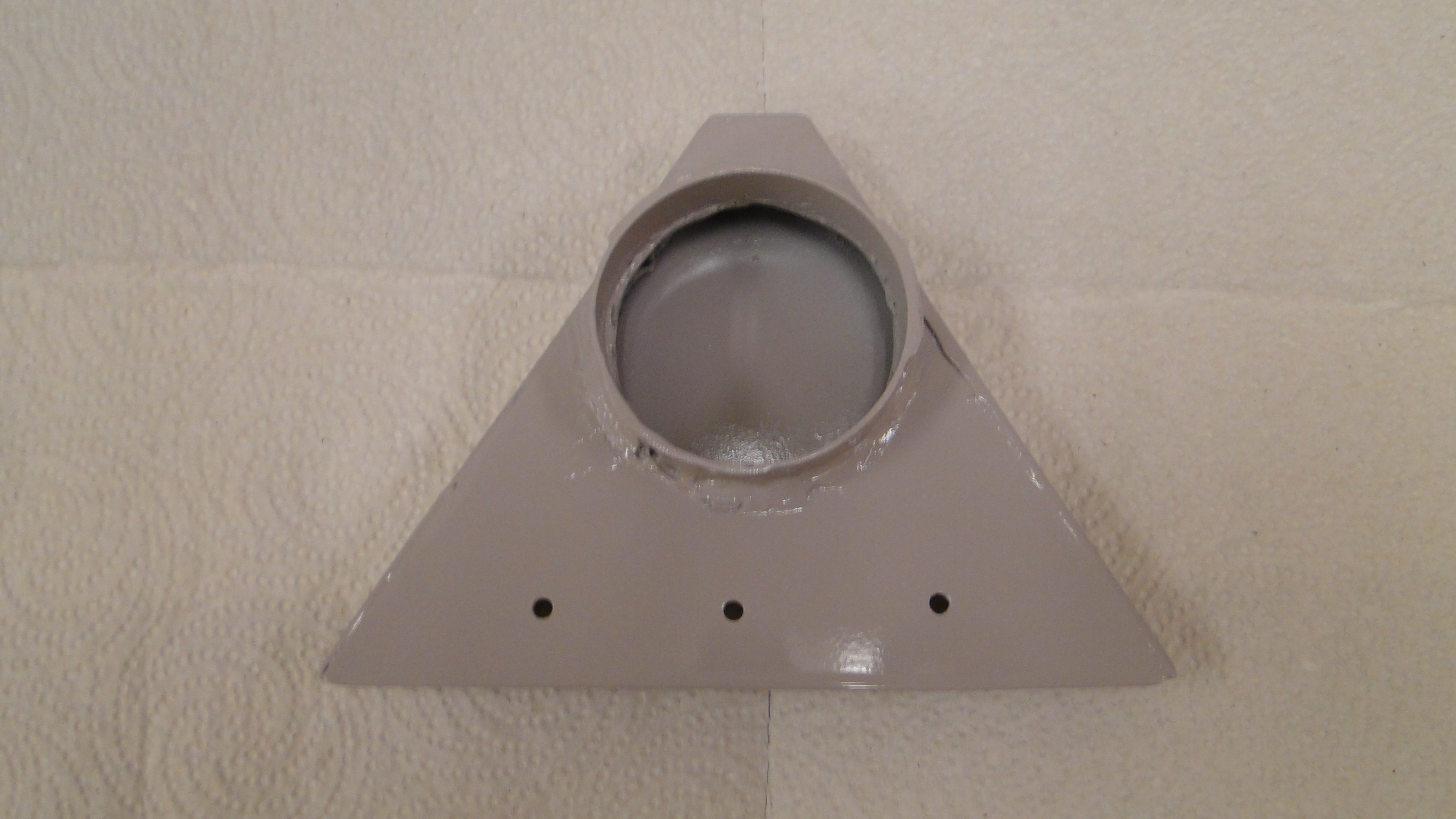
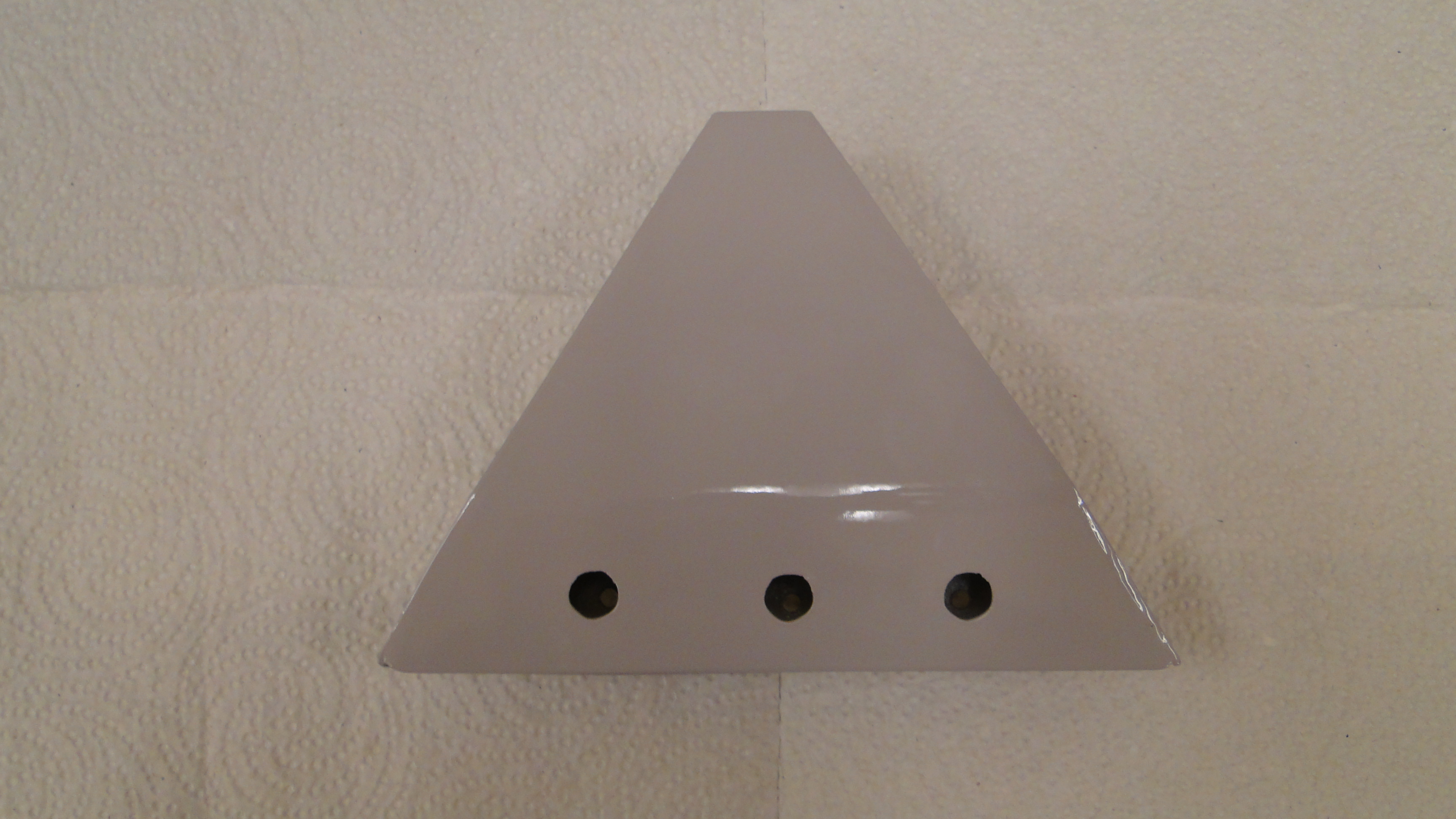
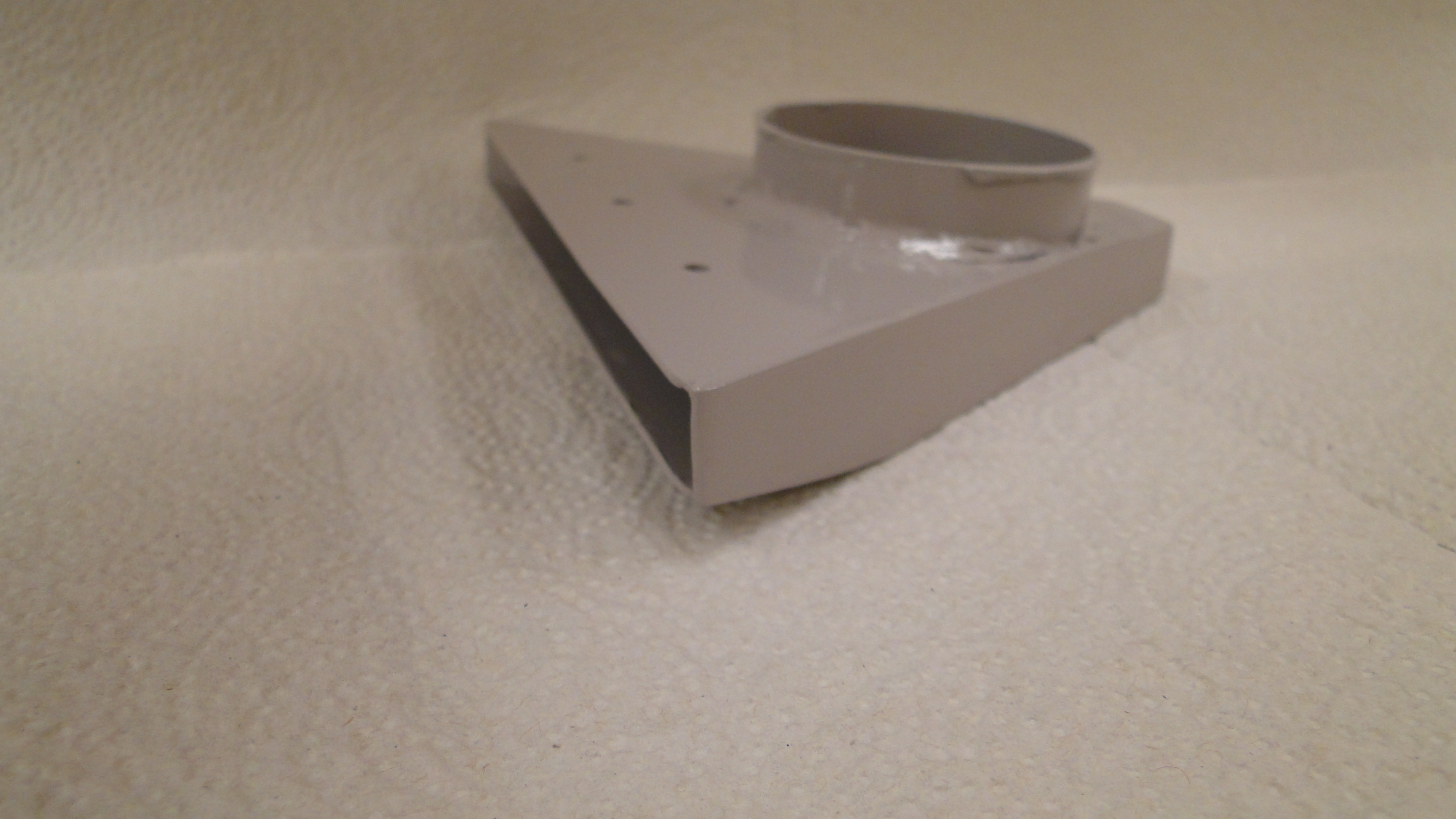
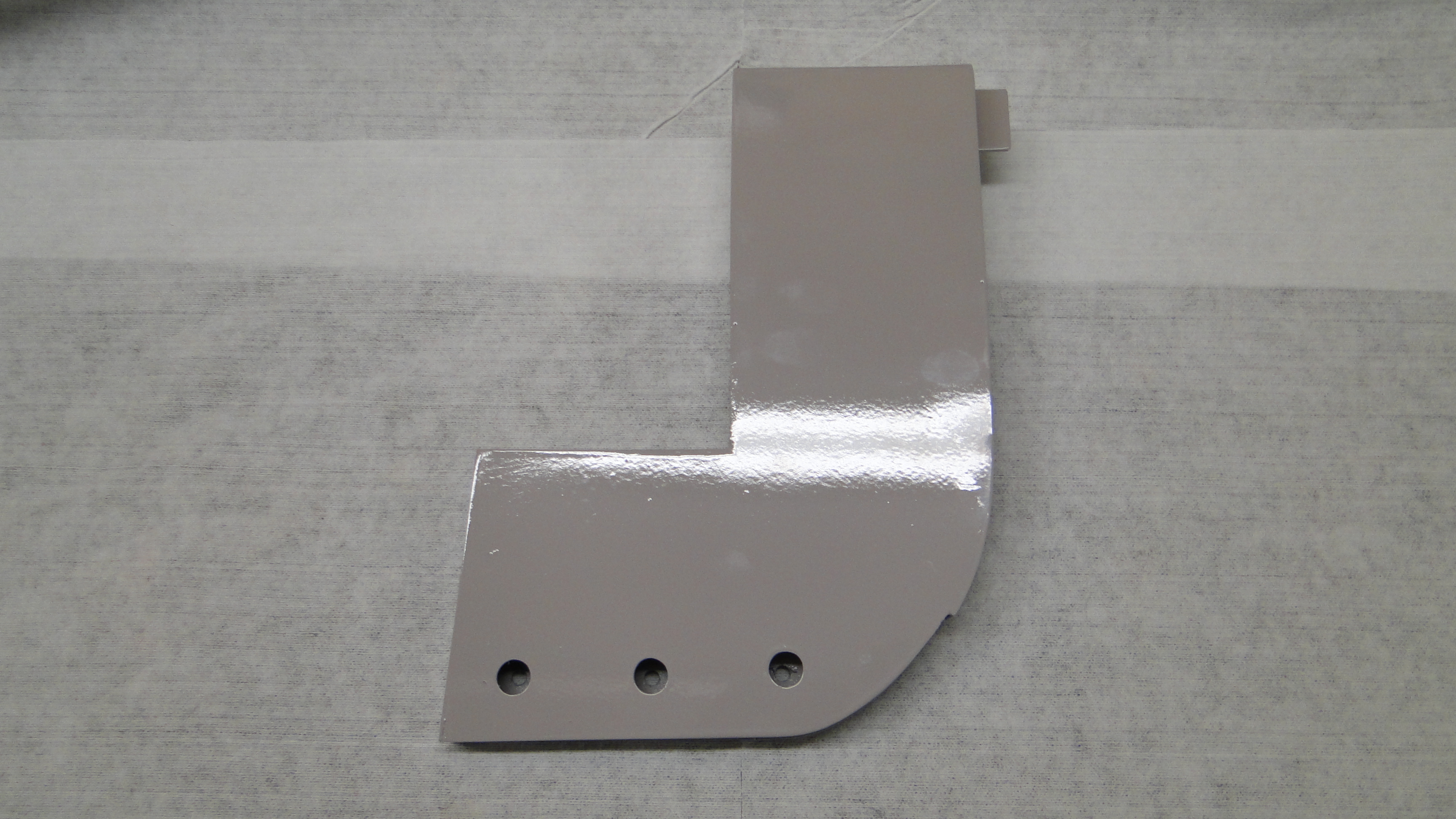
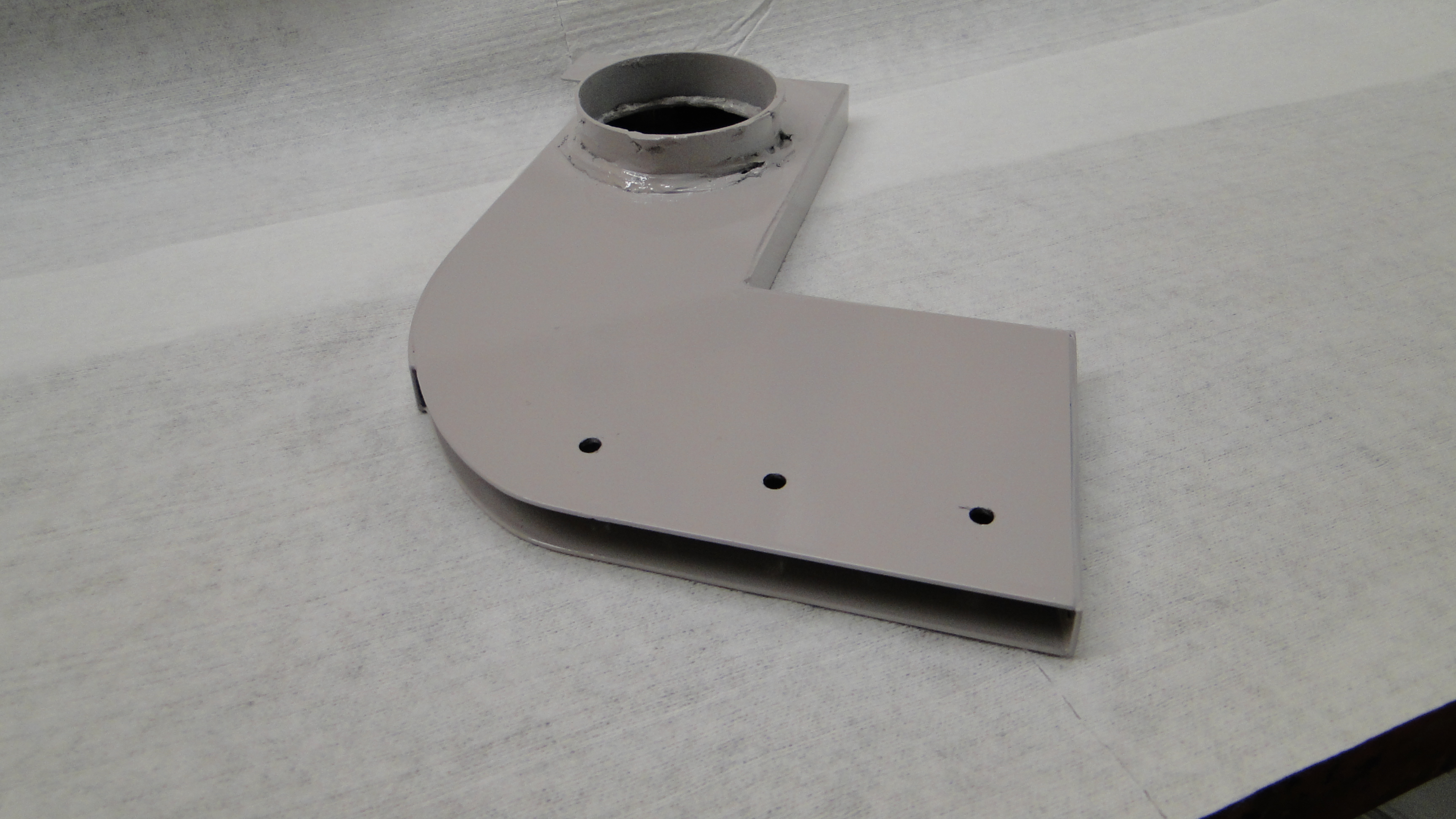
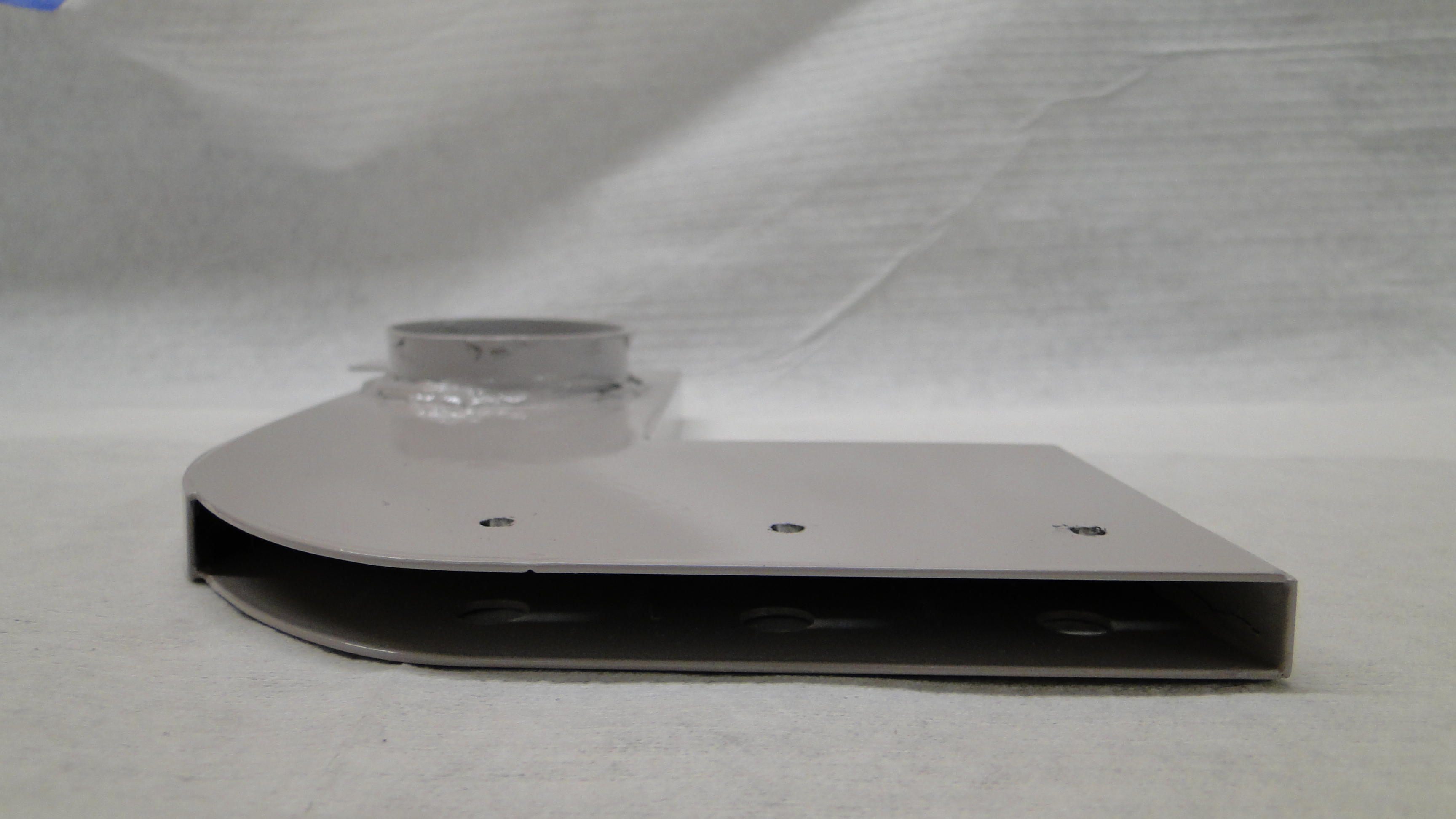
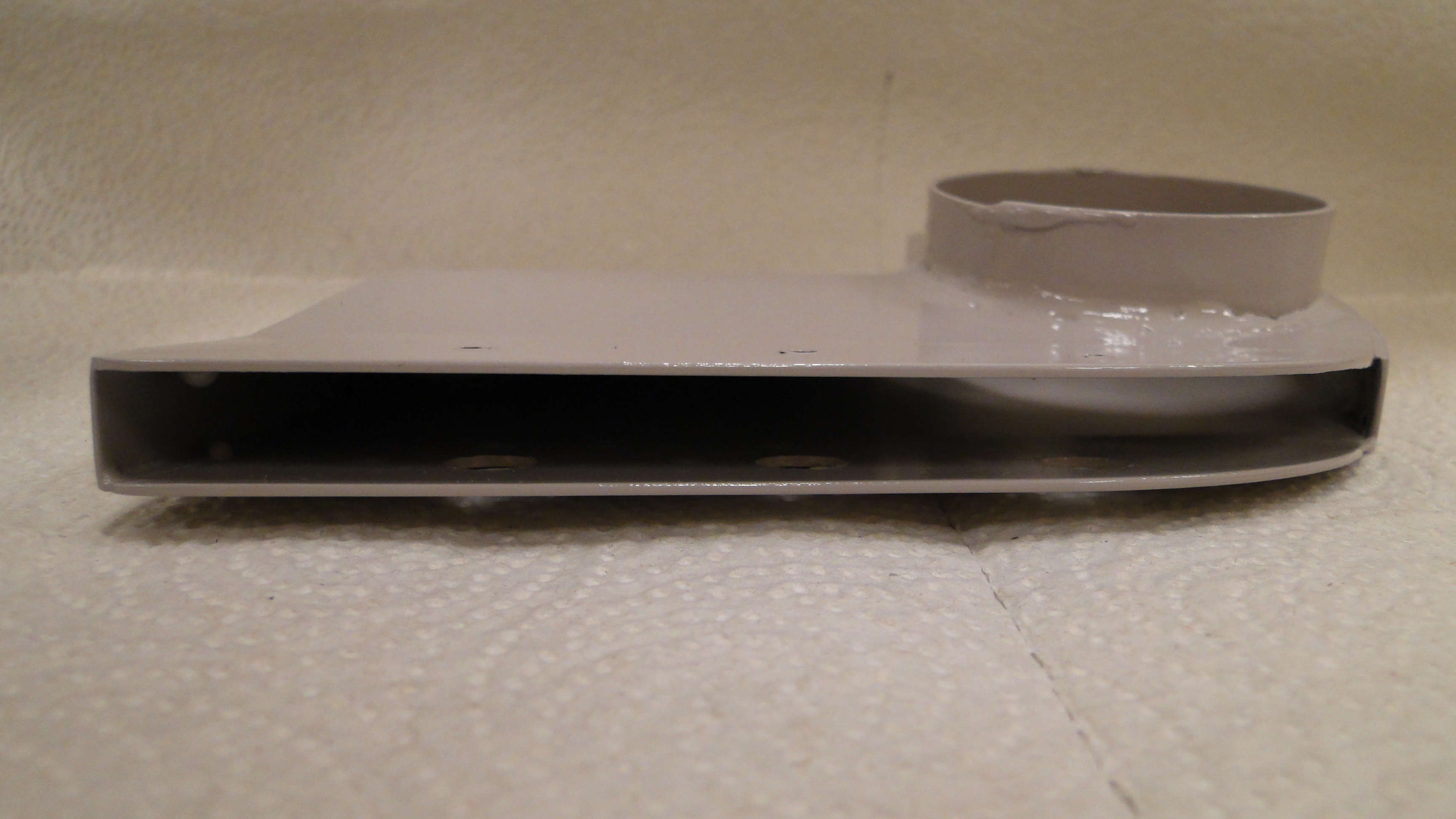
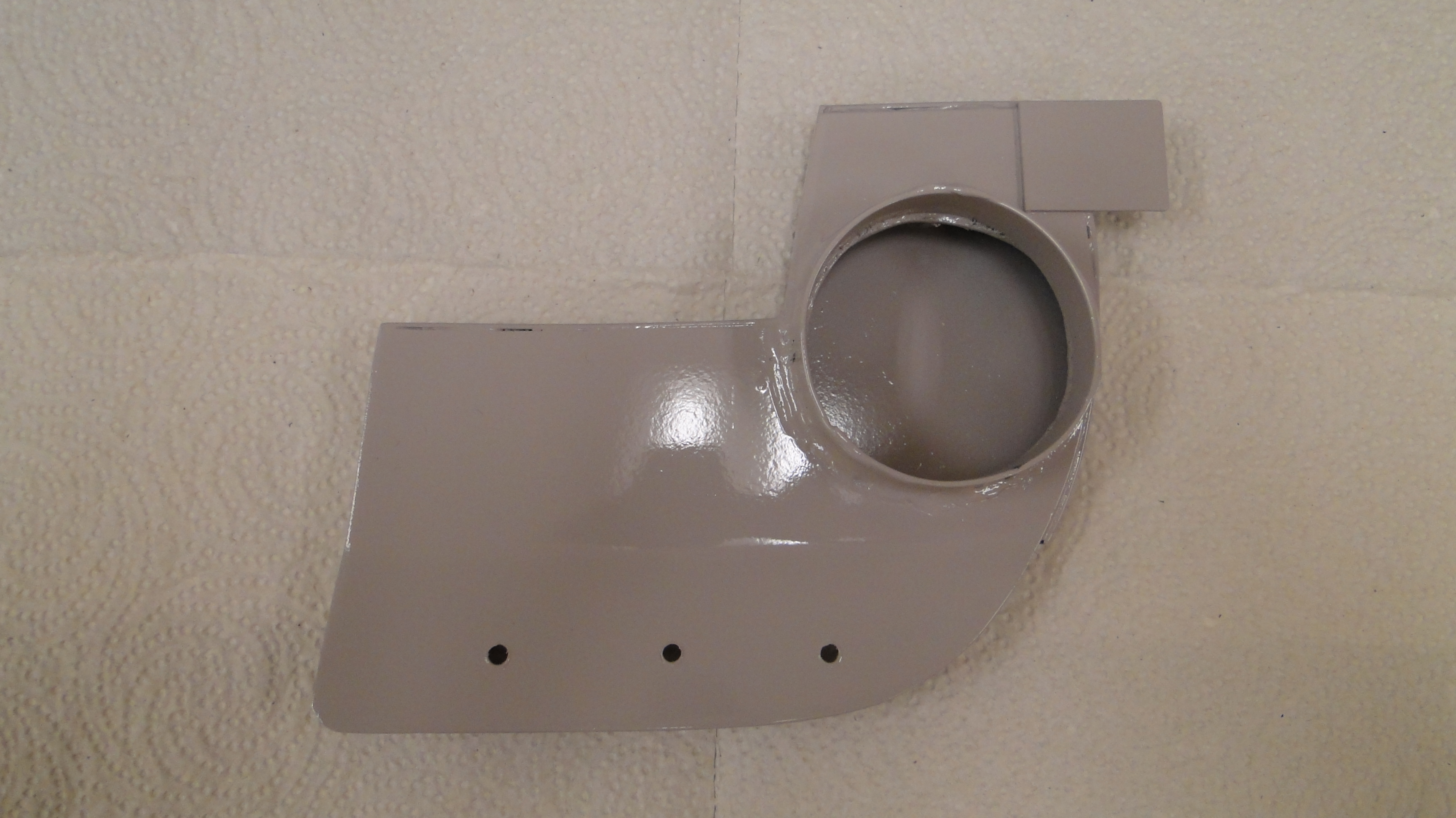
To mount the air tunnels I drilled small holes in the
top section for the screws, and larger holes in the bottom section. The larger
holes allowed my screw driver to have access to the top section for the mounting
screws. I noticed that the rear of the larger tunnels needed additional
vertical support, so I added a small flange to the top of the tunnels. This
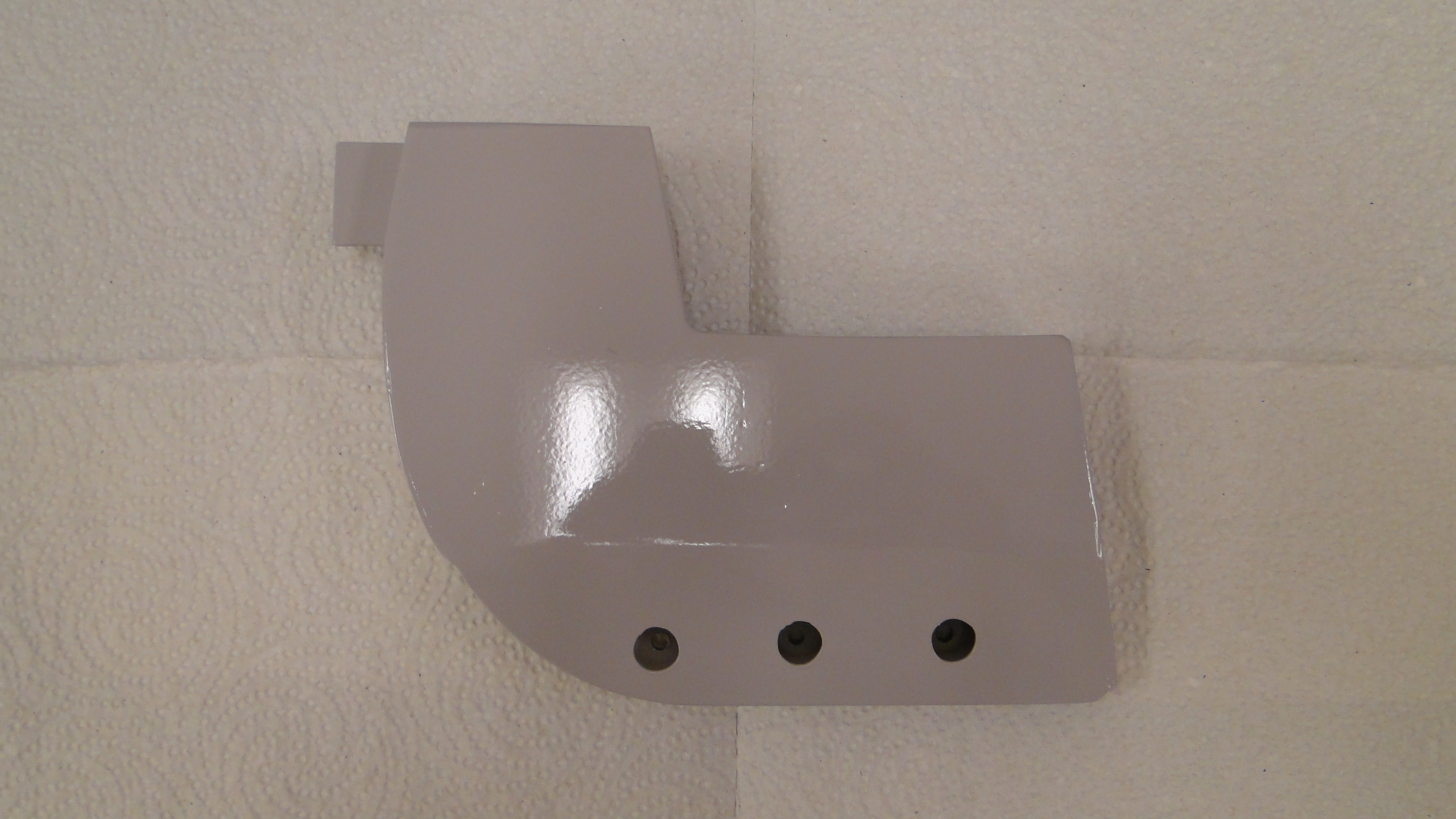
would allow them to sit on the top of an interior panel. I used body filler to smooth out the sides that showed.
Then primer was applied, and
finally the paint matching the Dash was applied.
Passenger Side
Click any picture to enlarge.
Center
Click any picture to enlarge.
Drivers Side
Click any picture to enlarge.
Front Views
Click any picture to enlarge.
Air Vent Dash Installation
Click any picture to enlarge.
Click picture to enlarge.
Click any picture to enlarge.
Click picture to enlarge.
Click picture to enlarge.
February
Finish Interior And Windshield Garnish Molding
Restoration And Installation
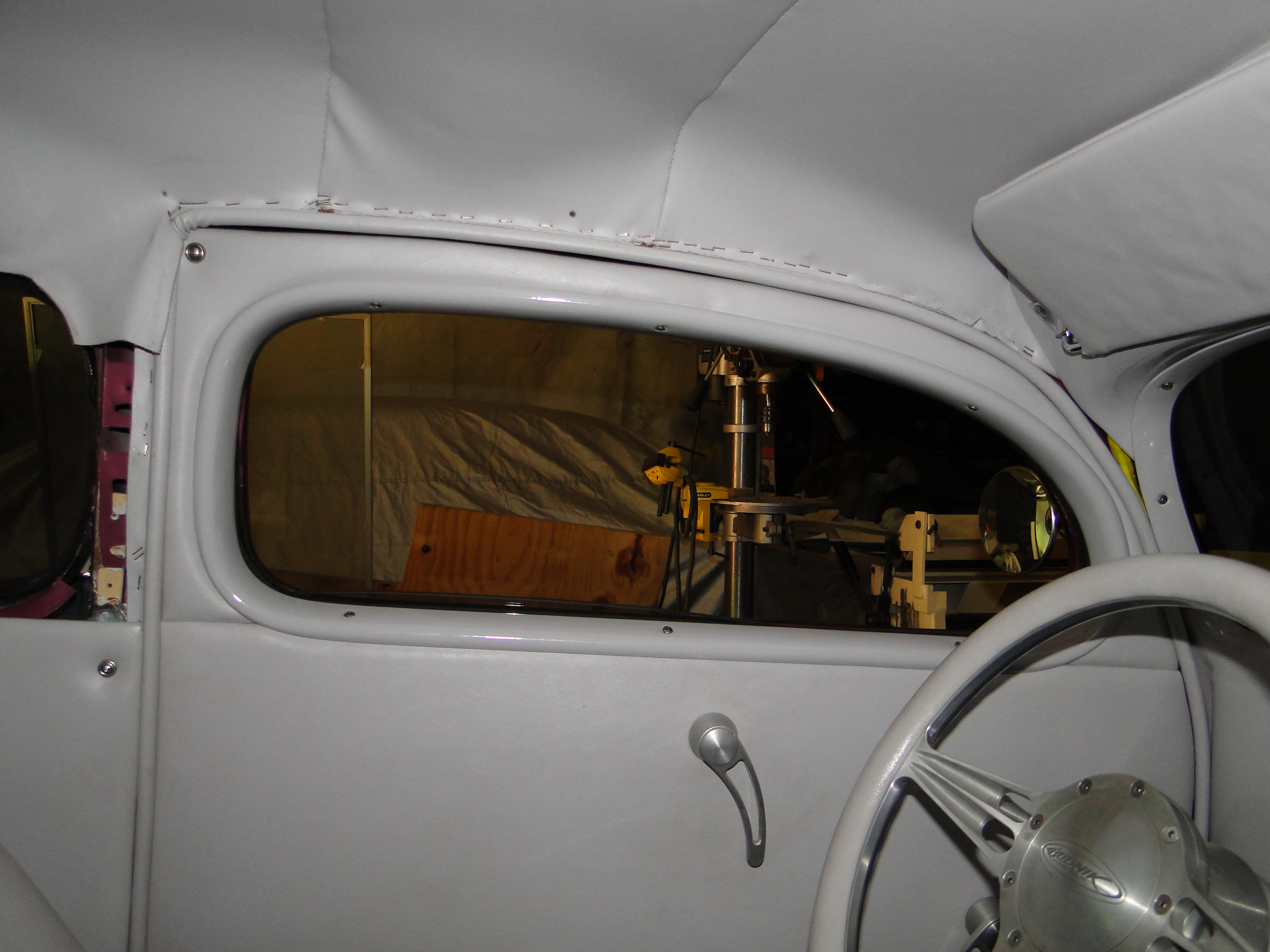
The interior work had to stop a few years back until I decided what to do with
the area above the door windows, windshield interior headliner and side posts, the roof had been lowered
approximately four inches which at the time seemed like no big deal.
You see I was not happy with what was done by the previous owner inside the car.
He did not use the original molding on the windshield or the side post and he made a large trim
piece to go across the top of the headliner that blocked my view of the road when I drove
the car. I needed to come up
with a new plan.
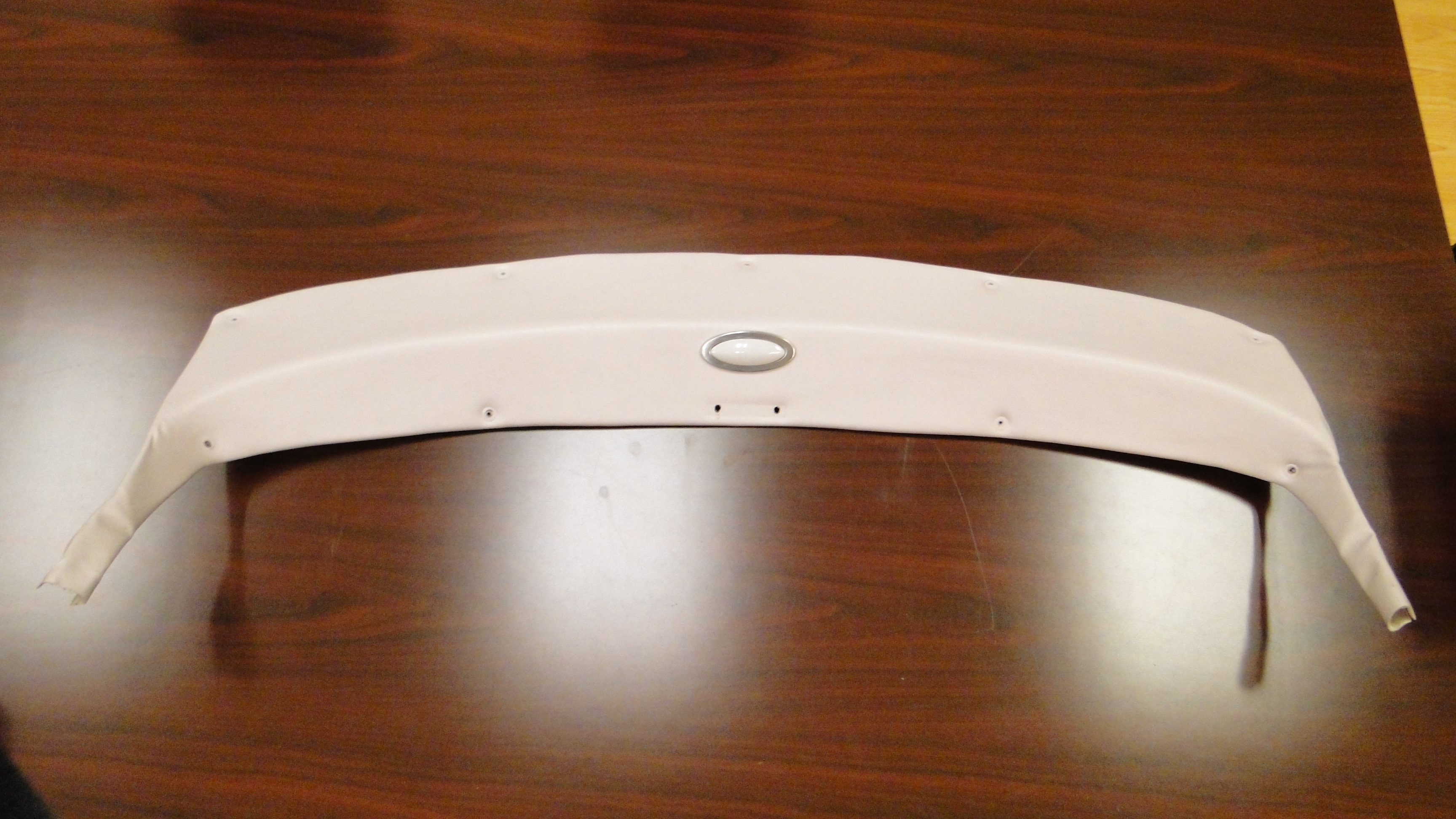
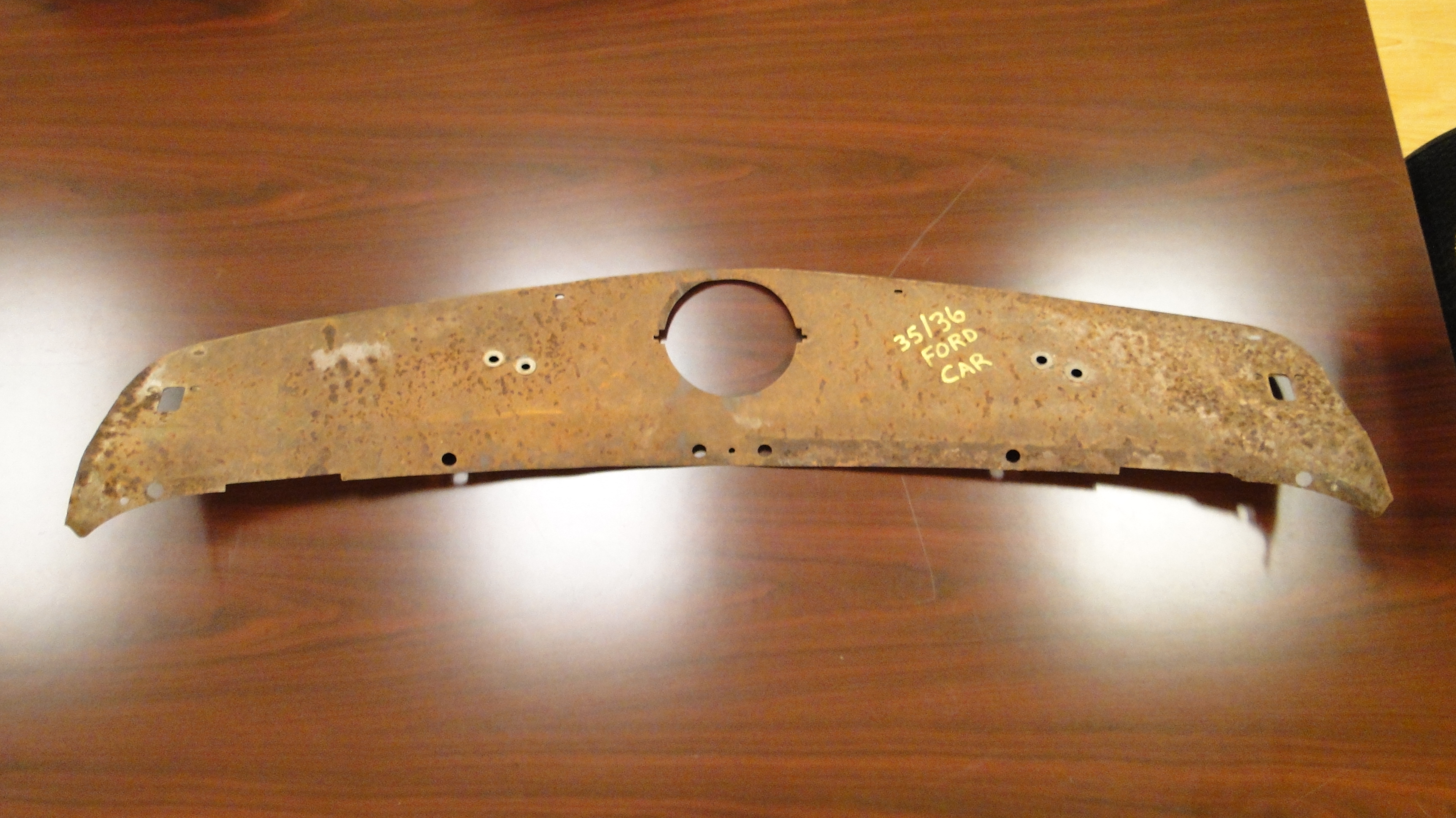
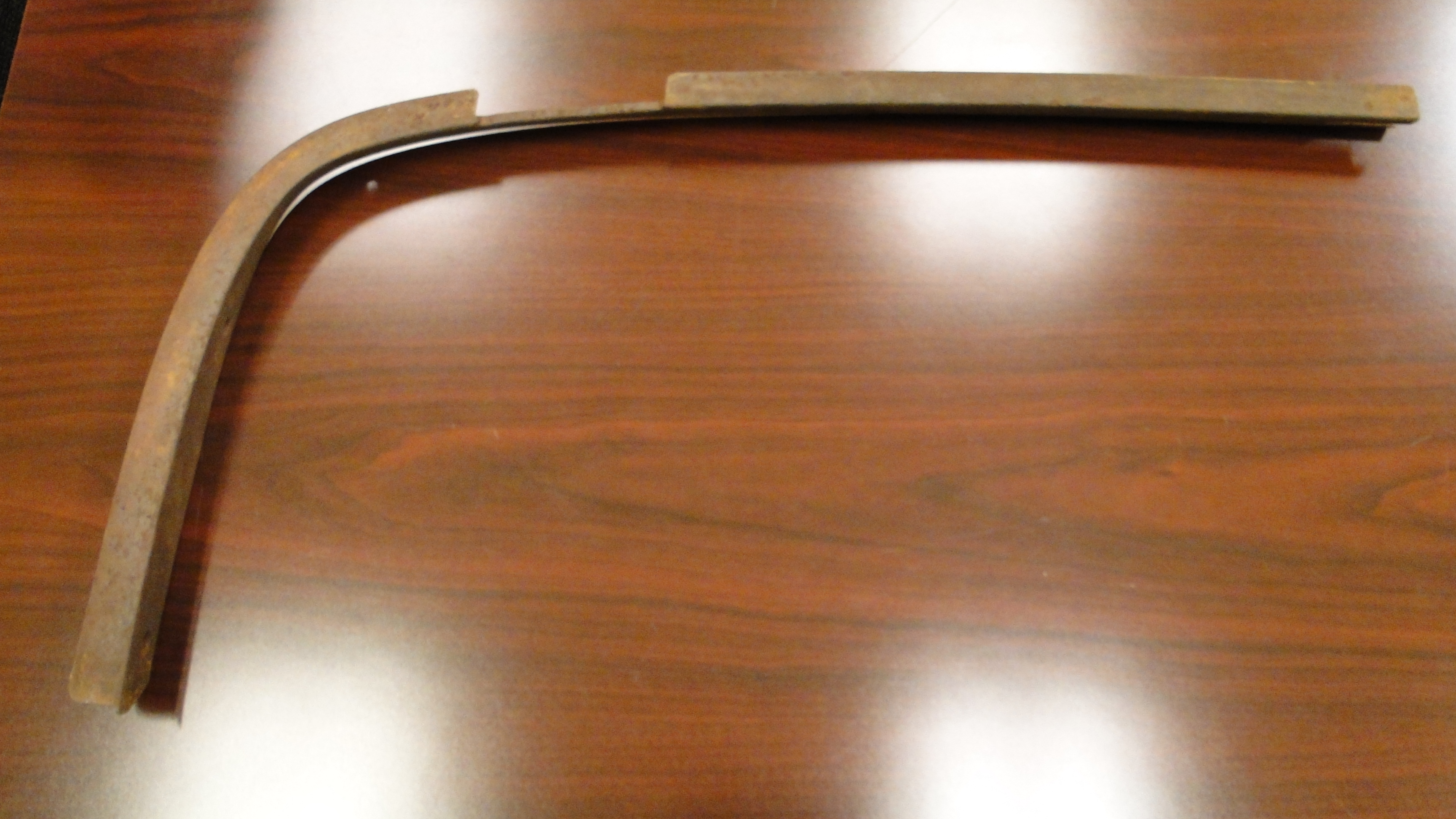
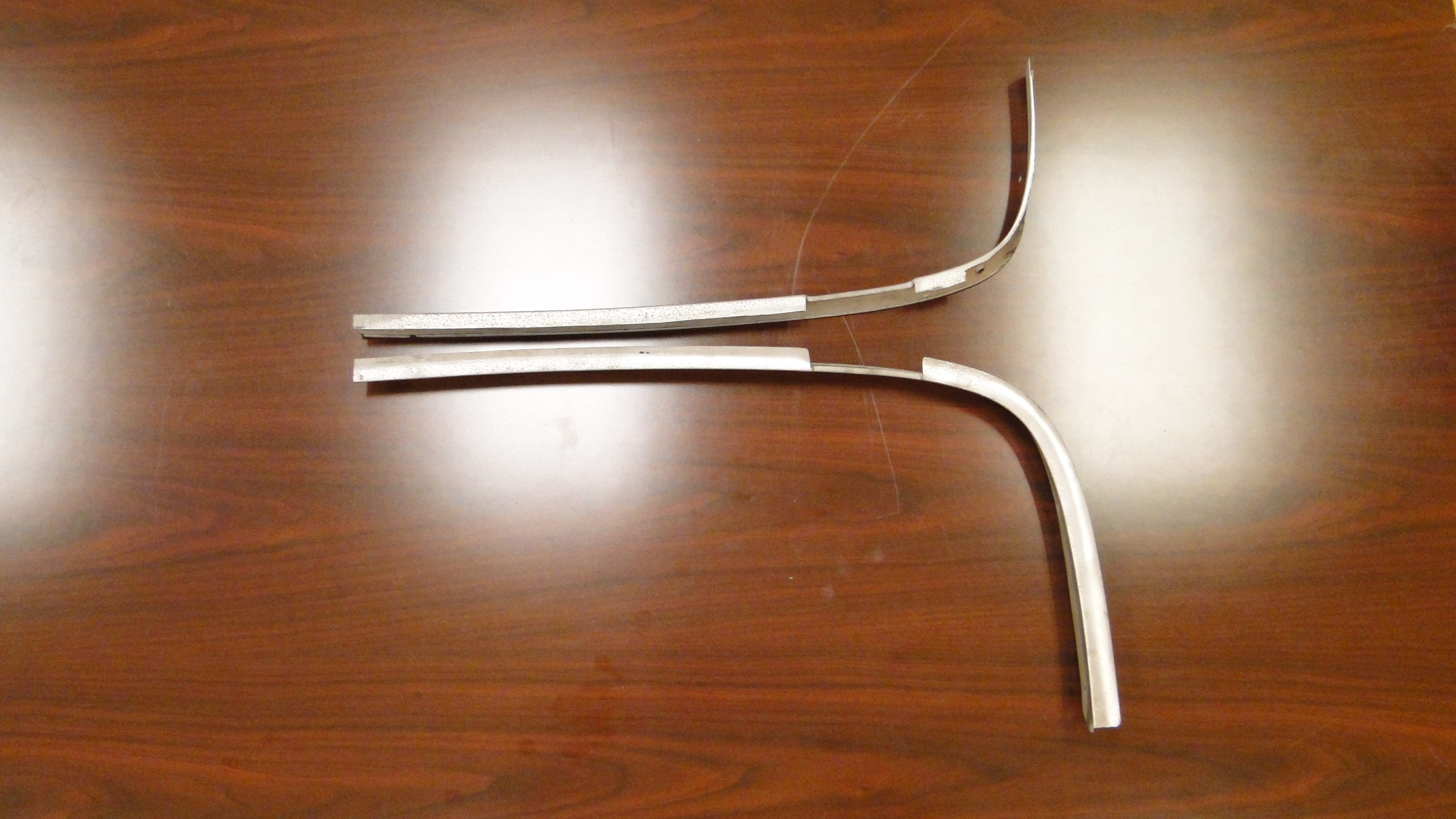
After months of looking every where I found two original garnish post moldings and one
original headliner molding in Colorado. They looked a whole lot better in the
photos before I purchased them. When I received all three parts they were in
really really bad shape, I thought this looks easy enough to put in. When I
tried to test install all three parts, nothing fit. I expected the post
moldings to be to long, however the shape and curves needed changed as well.
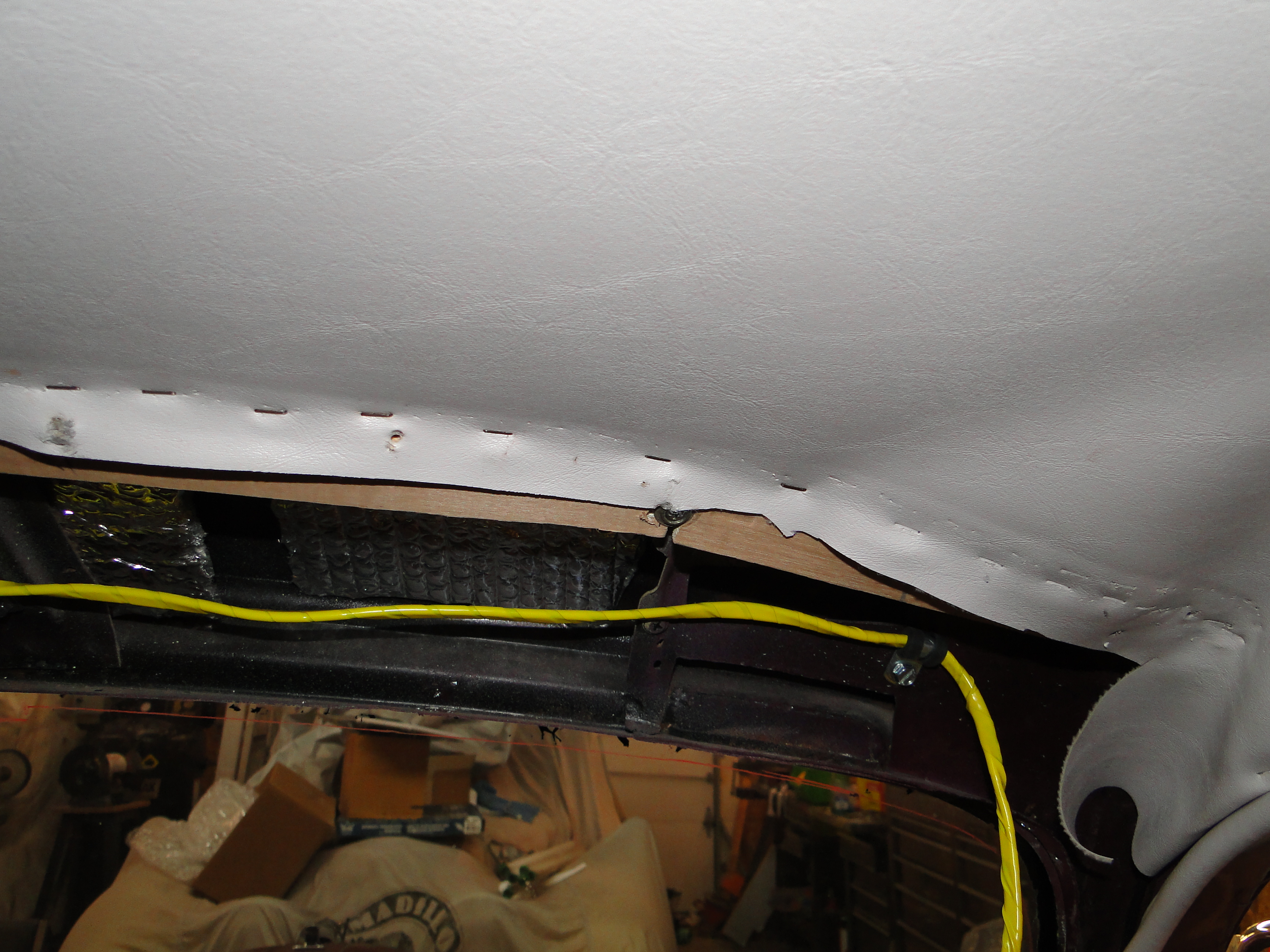
The large headliner molding part was 3/4 of an inch to short, at this point I
am thinking "What did I get my self into here"? I removed the homemade headliner
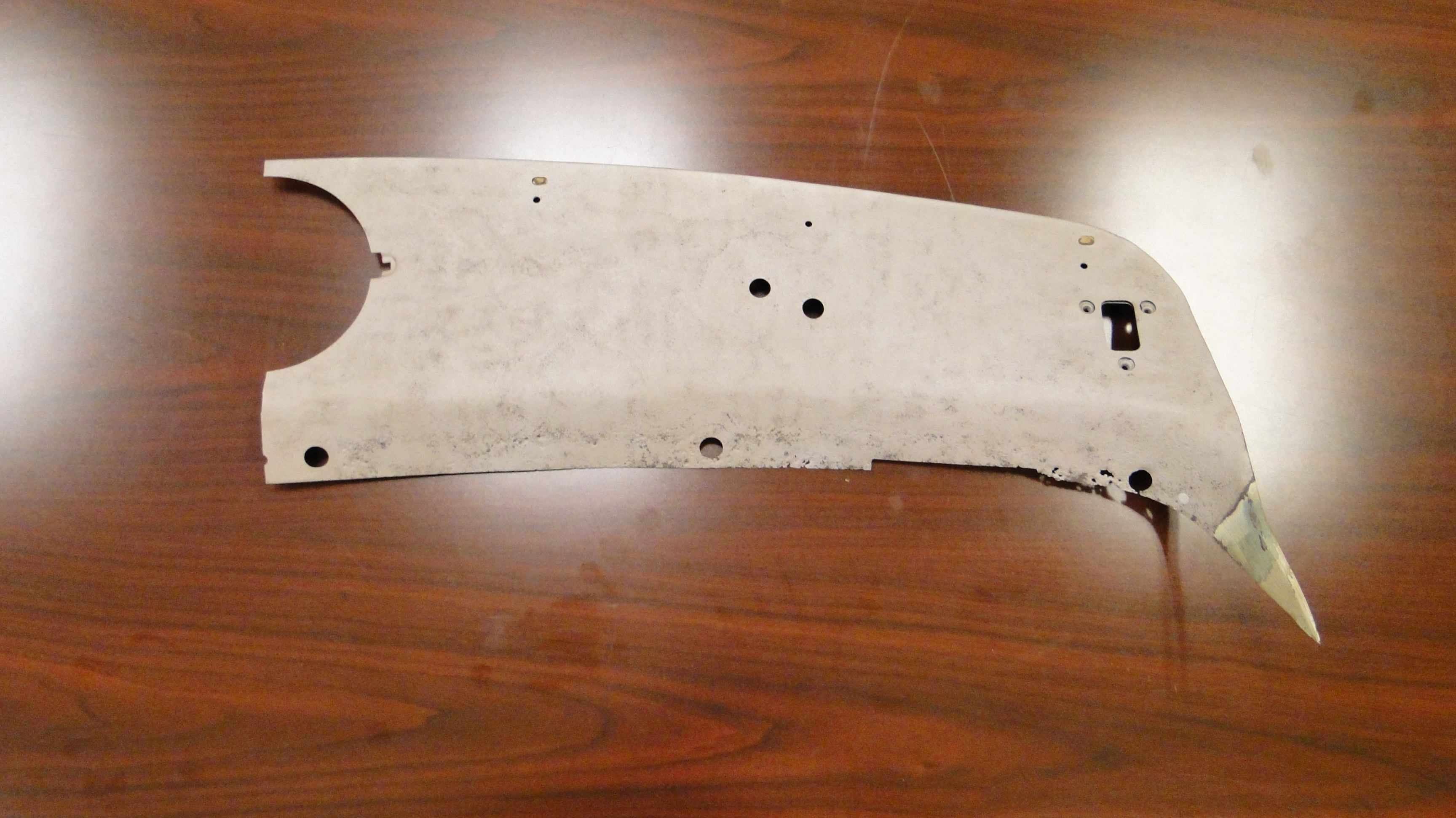
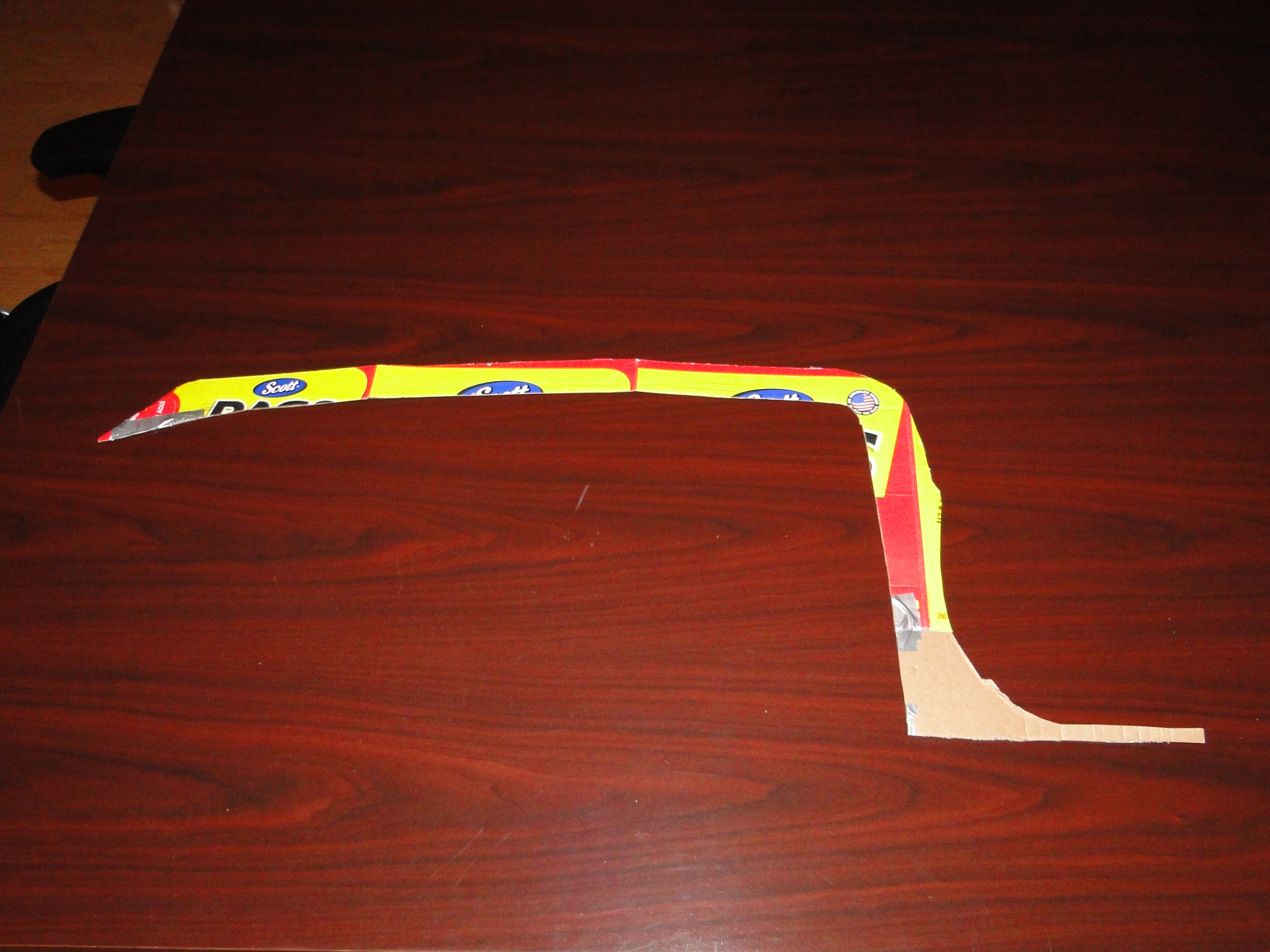
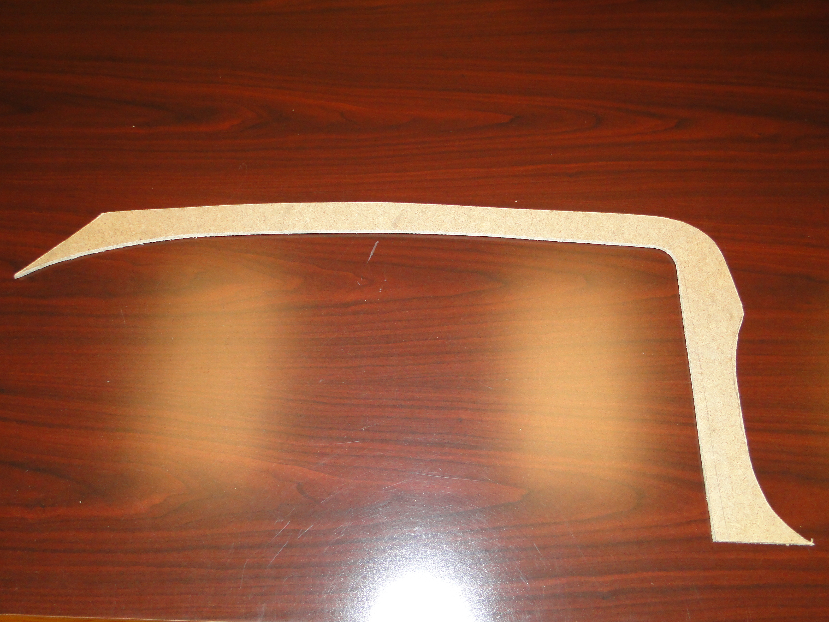
and started to modify the side post moldings to fit. I had to trim the
length and remove a large portion of the lip that goes between the glass and car
so I could bend them to fit properly. See photos
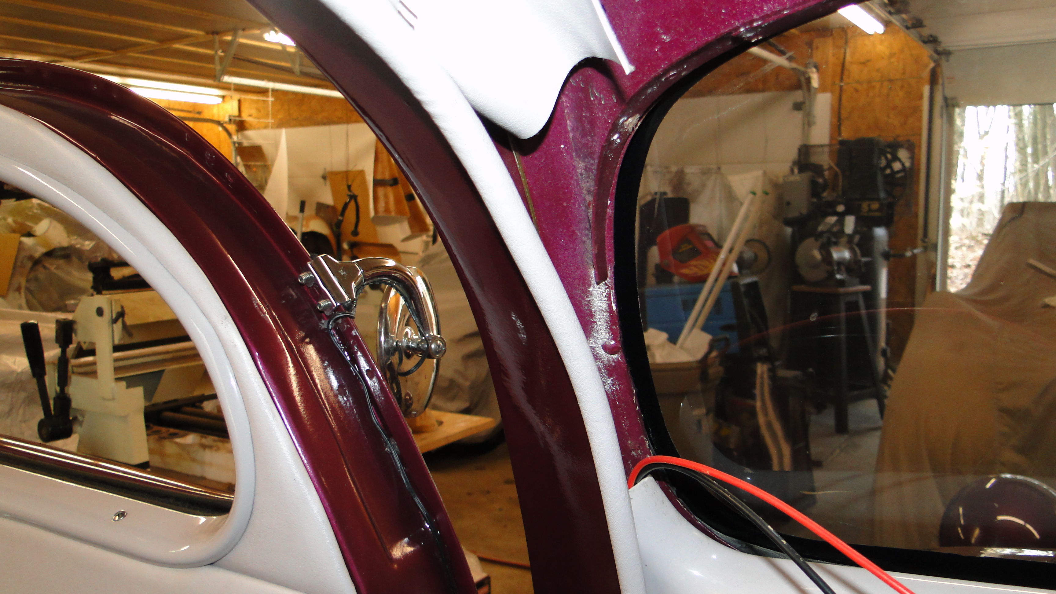
What I think has happened is, and this is just a guess at this point, the
previous owner had to change the windshield post angles to meet the roof four
inches sooner than it was designed. This changed everything and
that's why he made the old headliner molding out of fiber board for the interior
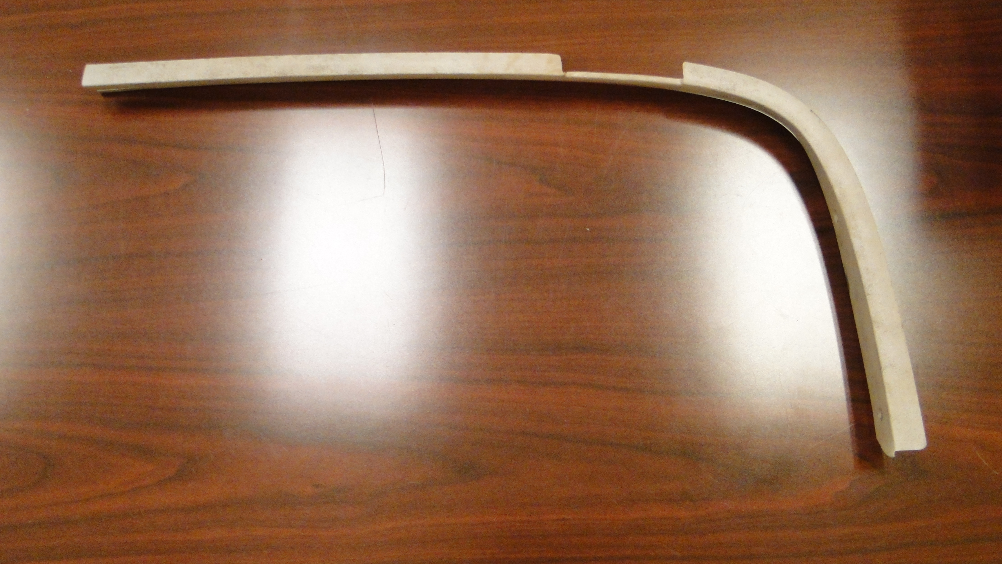
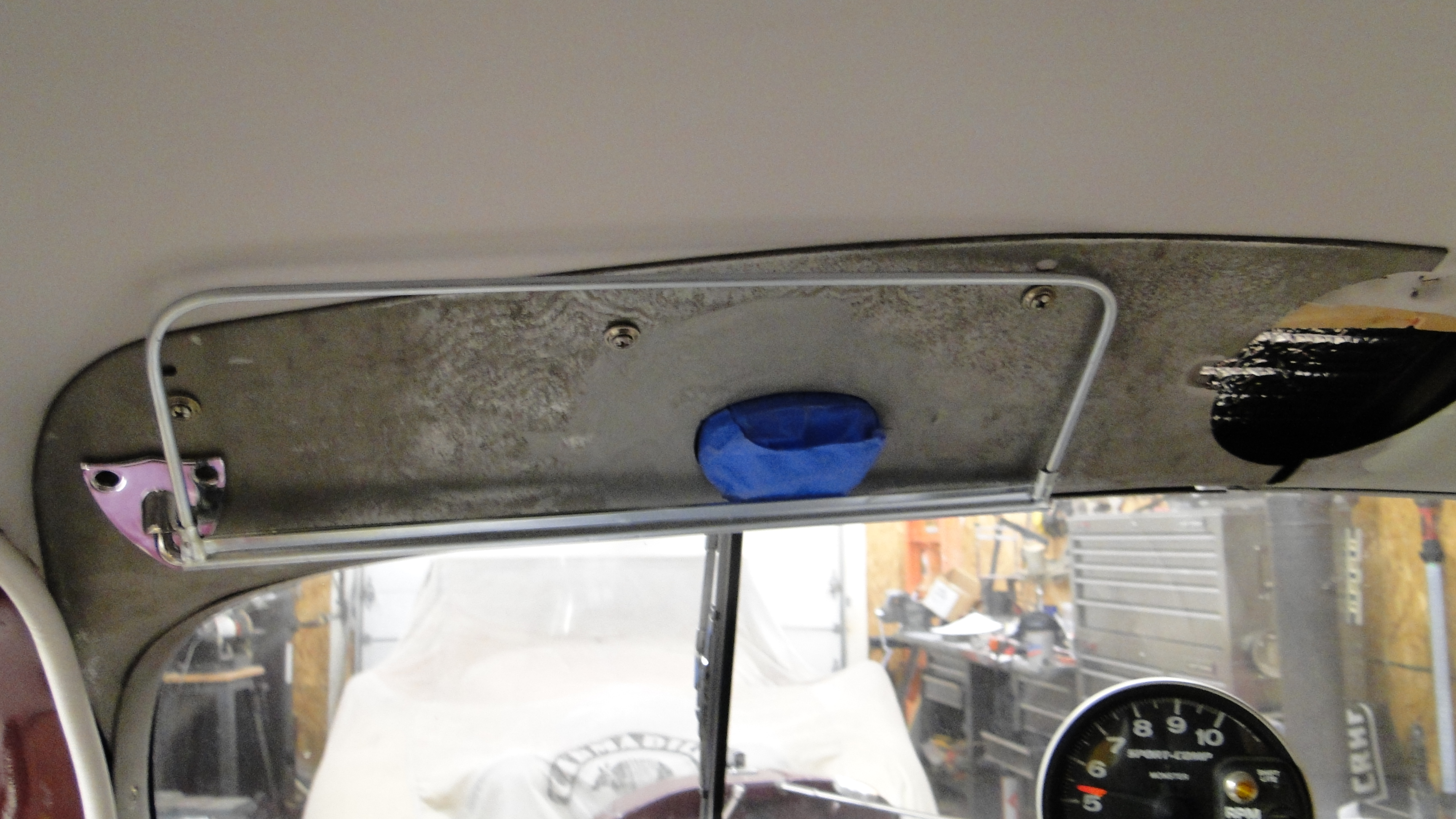
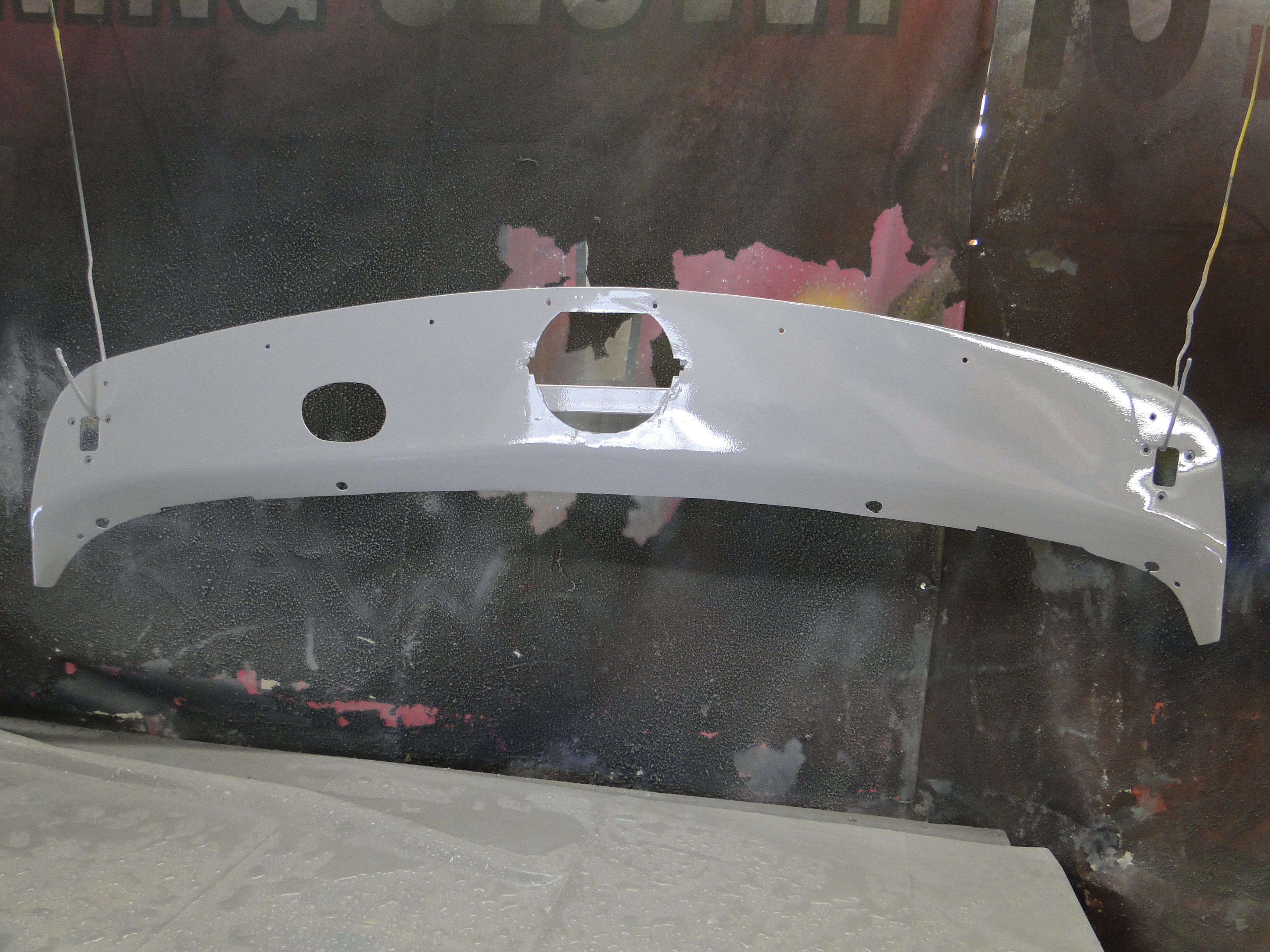
instead of re-using the original parts. First things first I had to hammer
out the dents and waves. Next the headliner molding is not designed
for a electric windshield wiper motor, so I had to cut a hole to accommodate
that.
Finally the headliner molding is too
short by 3/4 of an
inch, so I cut it in half right down the center so I could widen it to fit. See
photo.
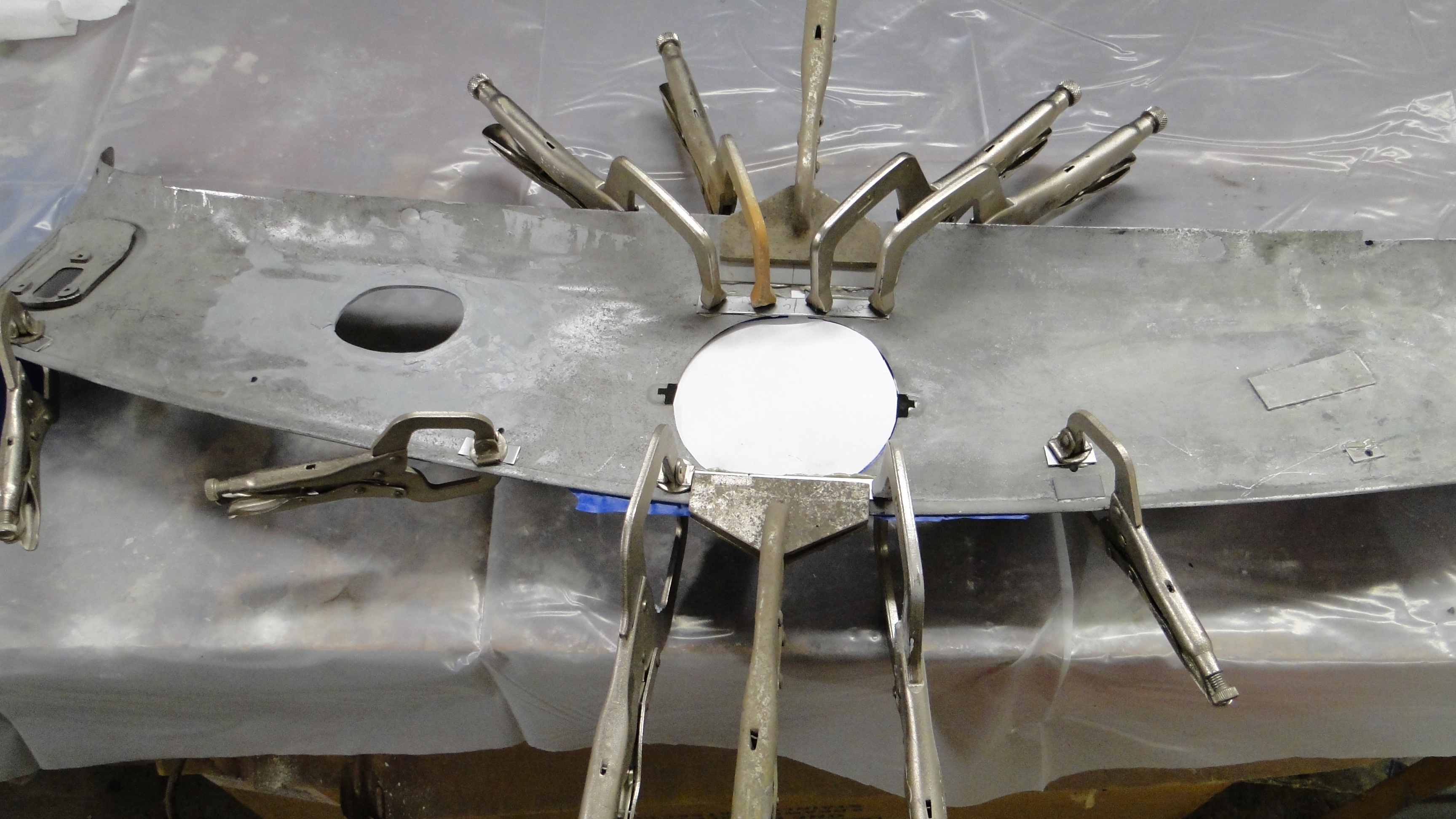
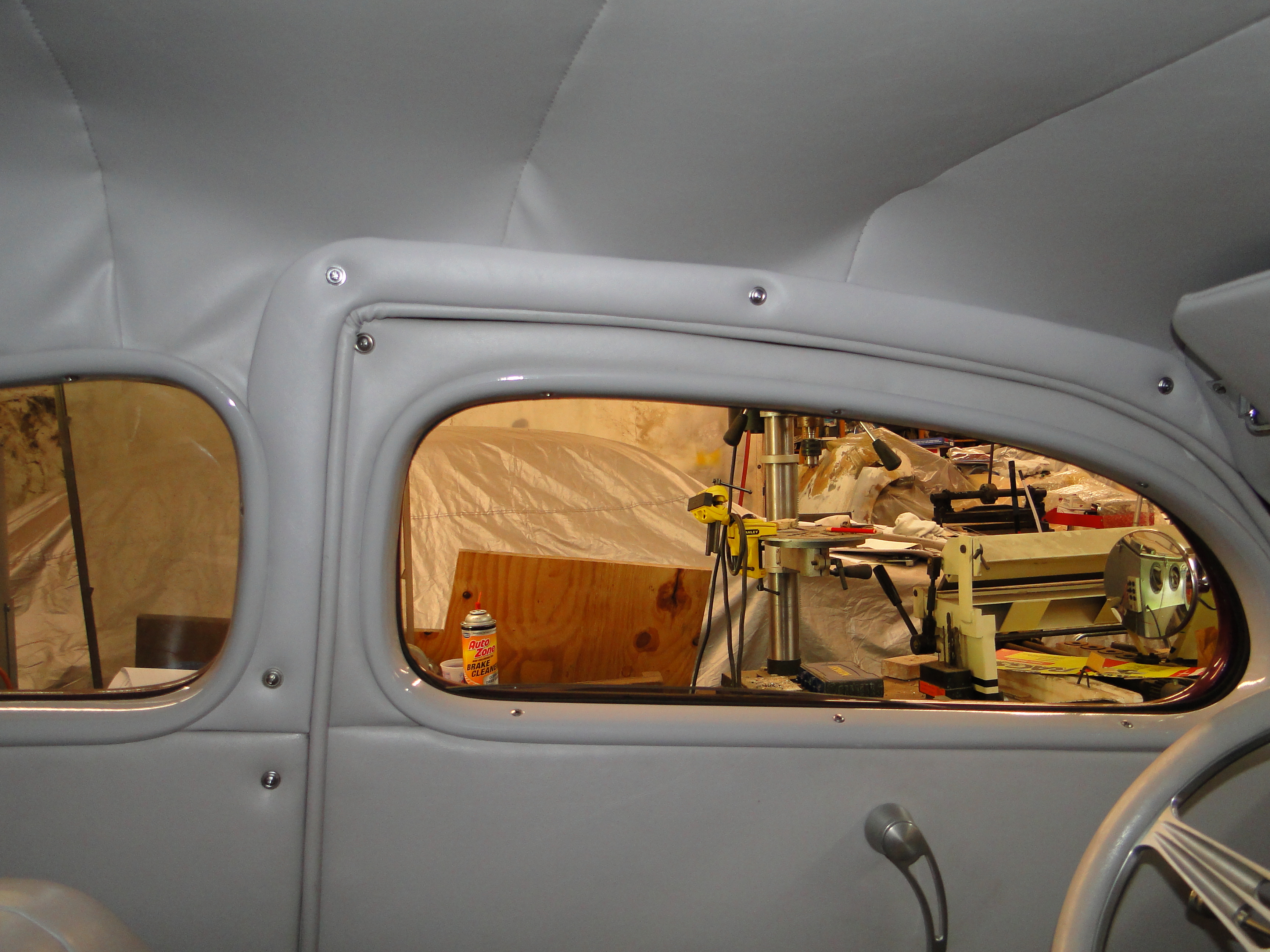
I had great success with Fuser adhesive on the air conditioner vents, so I
decided to use it again for this project.
I added a little filler to blend the posts with the
headliner, and we seem to be good to go for my first ruff fit test.
Once I was happy with the fit it was time to glue both half's together.
Click any picture to enlarge.
Click any picture to enlarge.
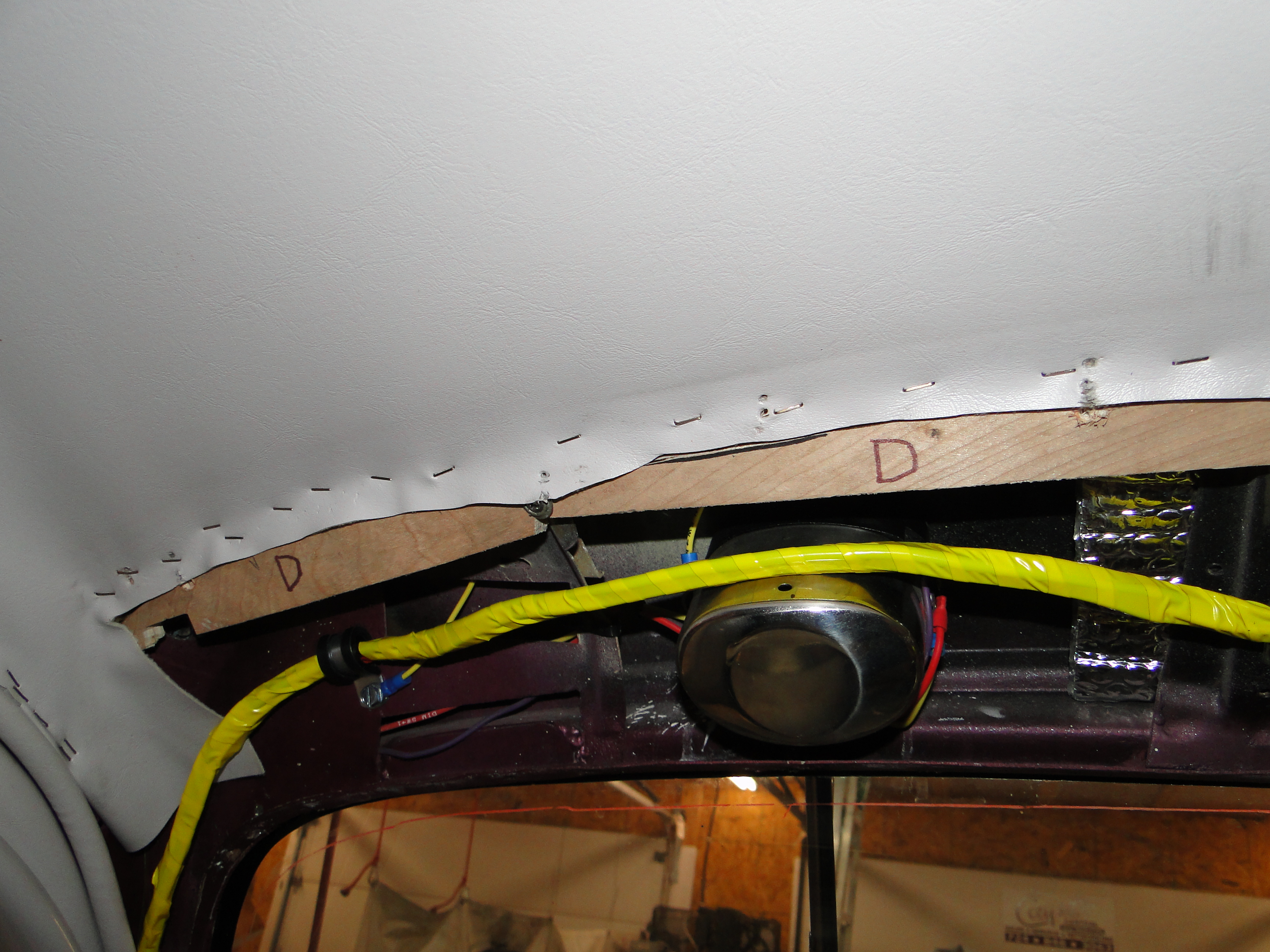
March
Console Fabrication
When I went to attach both headliner half's it quickly
became obvious to me that the previous owner did not make sure the wood strips
that the headliner mounts too were parallel with the windshield going across
the car. At this point I had to cut and add more wood strips for the headliner to
mount too. I needed to make up for the missing inch and a half gap difference from the
windshield on the passenger side, an then I could attach the new headliner trim
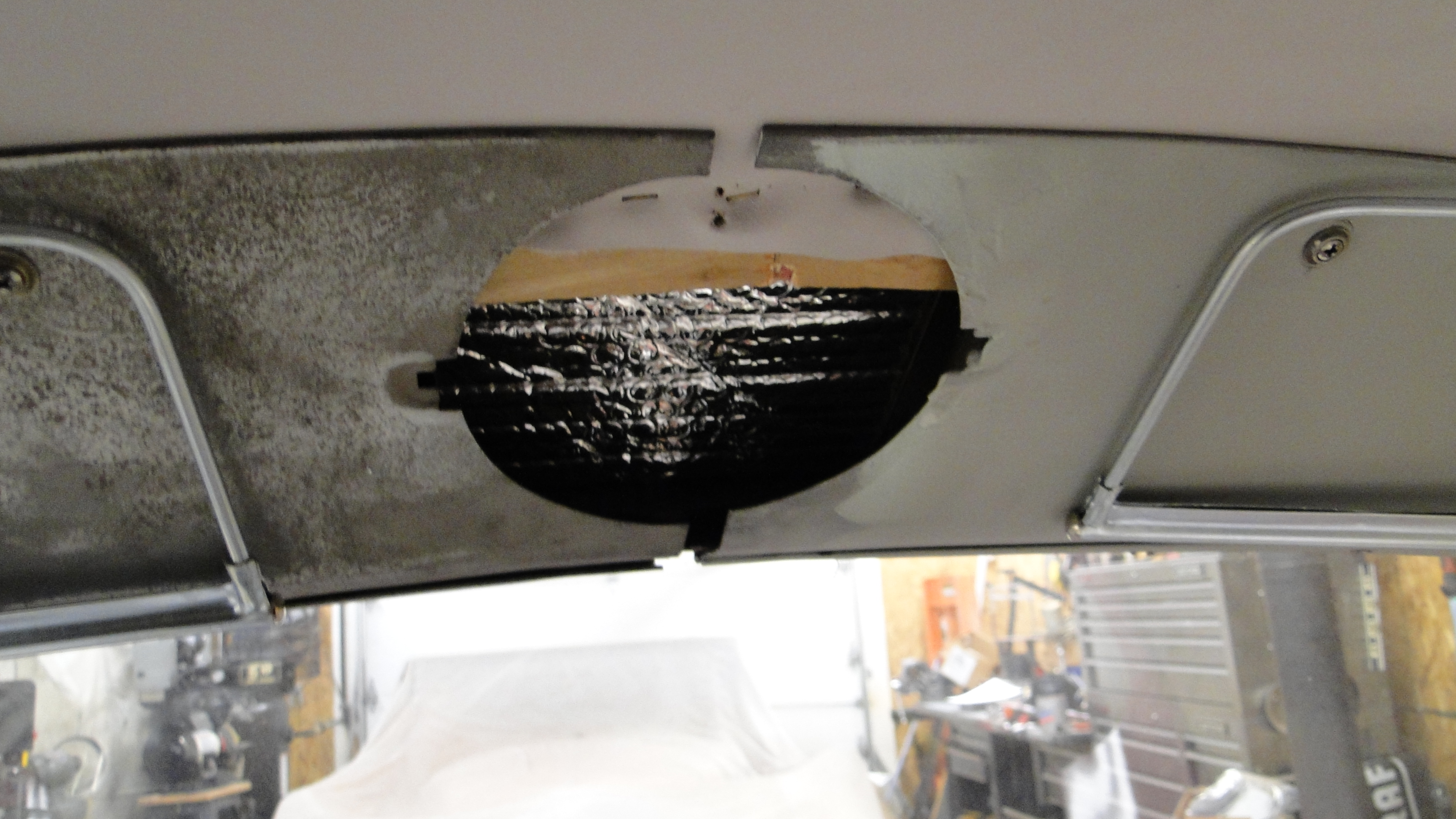
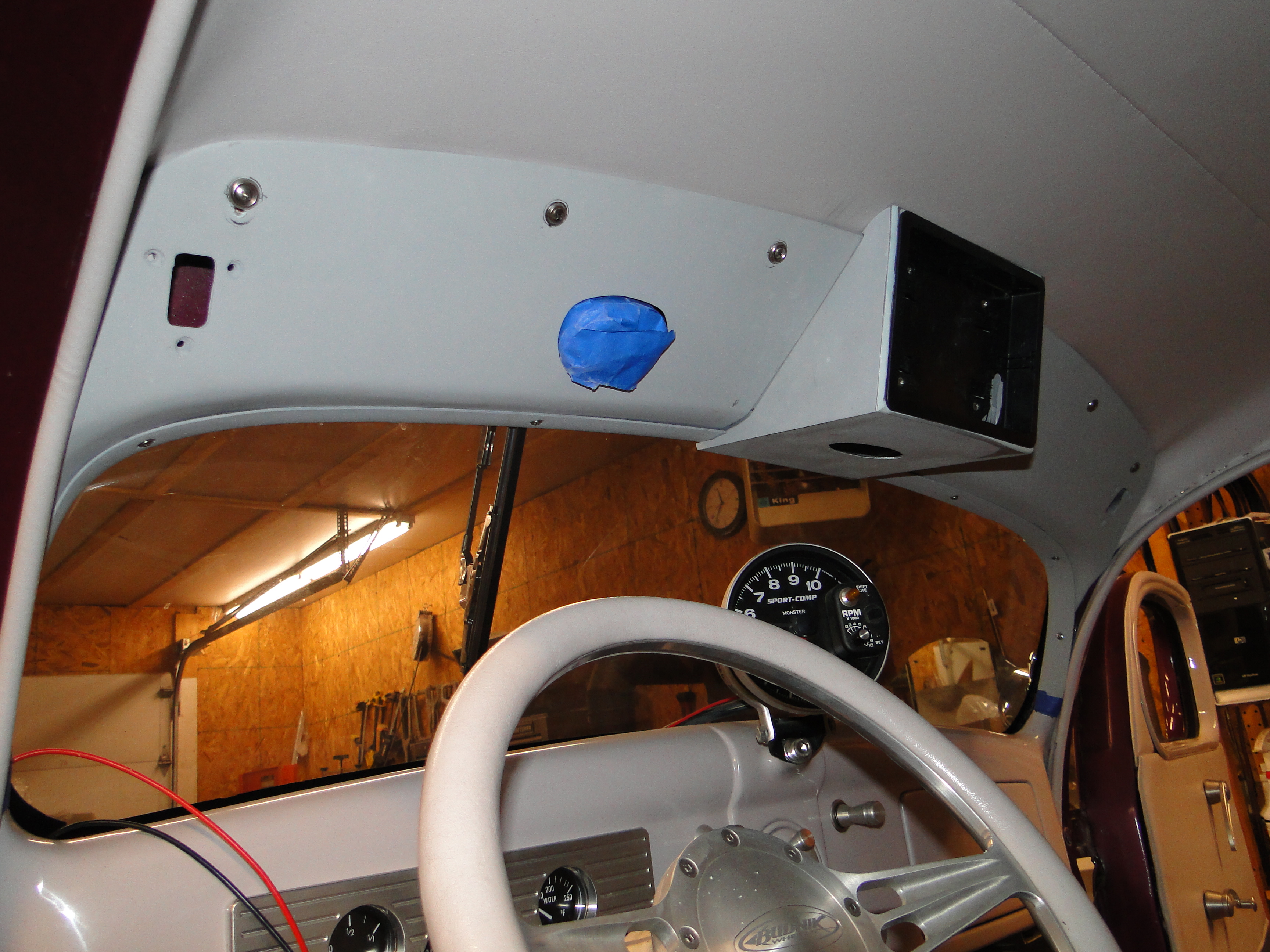
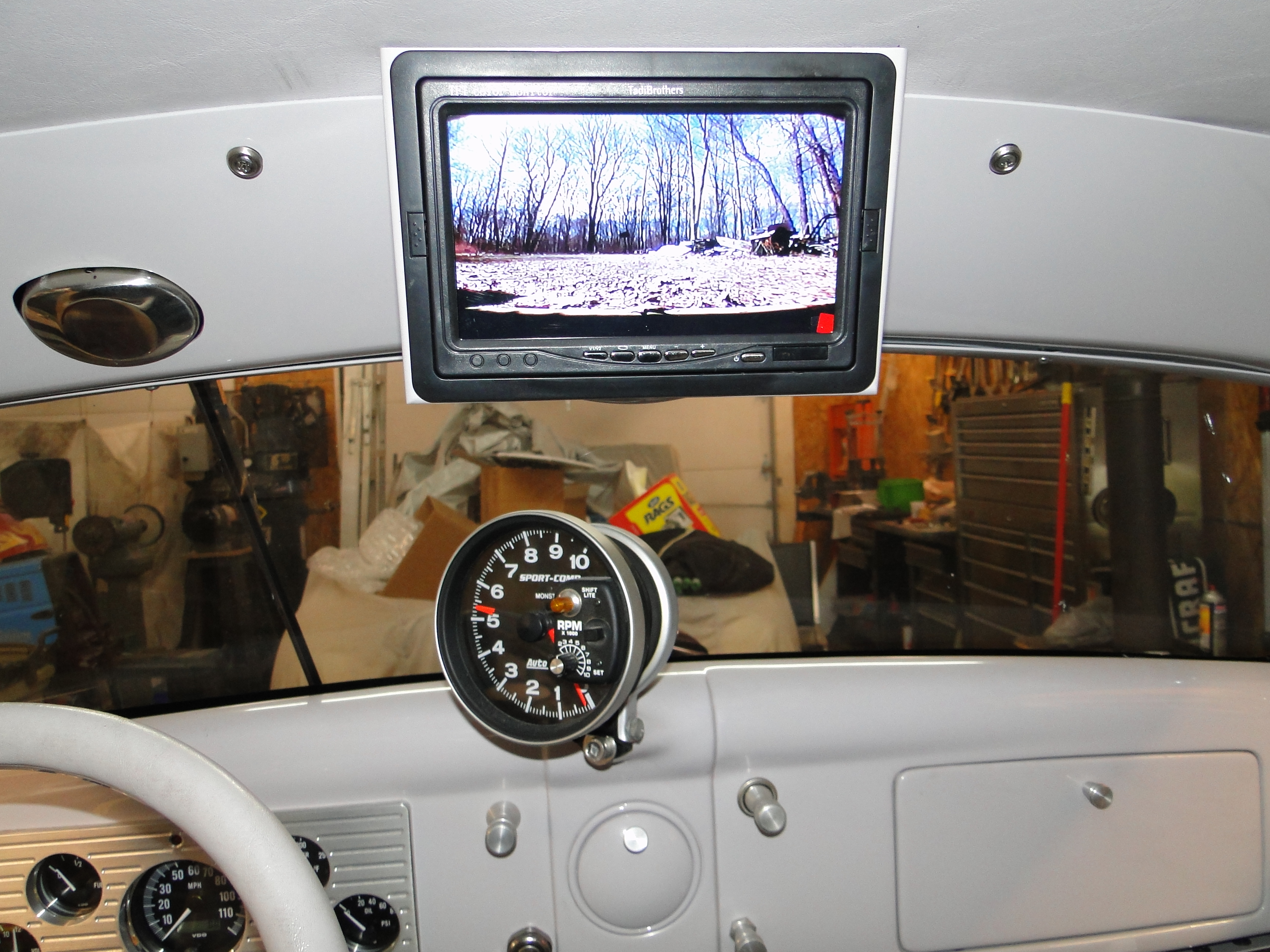
to the car. Now for the tuff part I
have to find a place for the interior cab light and add a digital rear view mirror, because I really
cant see any traffic out the tiny rear window at all, because I have had a few near
collisions when I was trying to change lanes. This is what has to
happen, I need to fit the the digital screen over top the original Radio speaker area, and
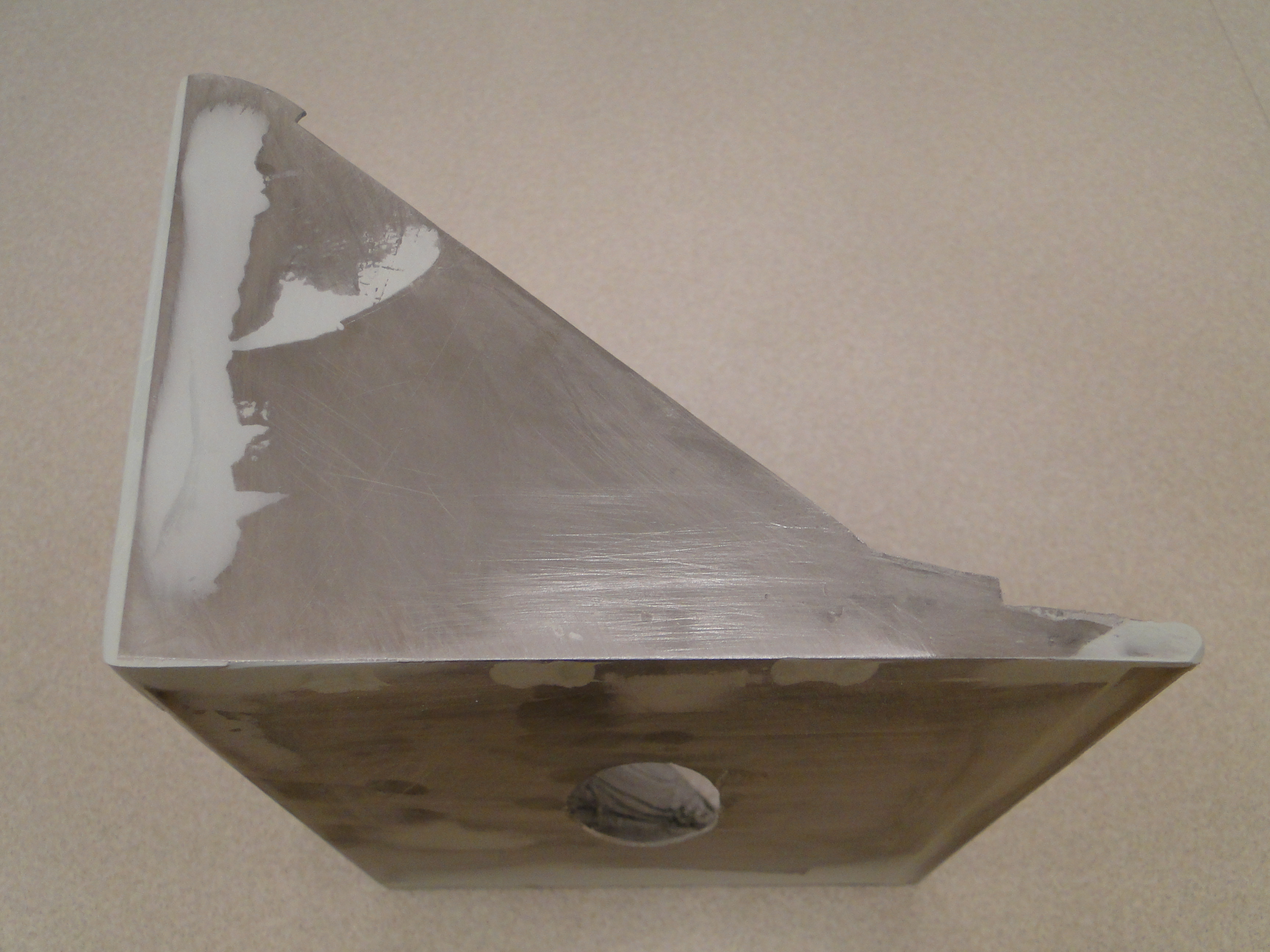
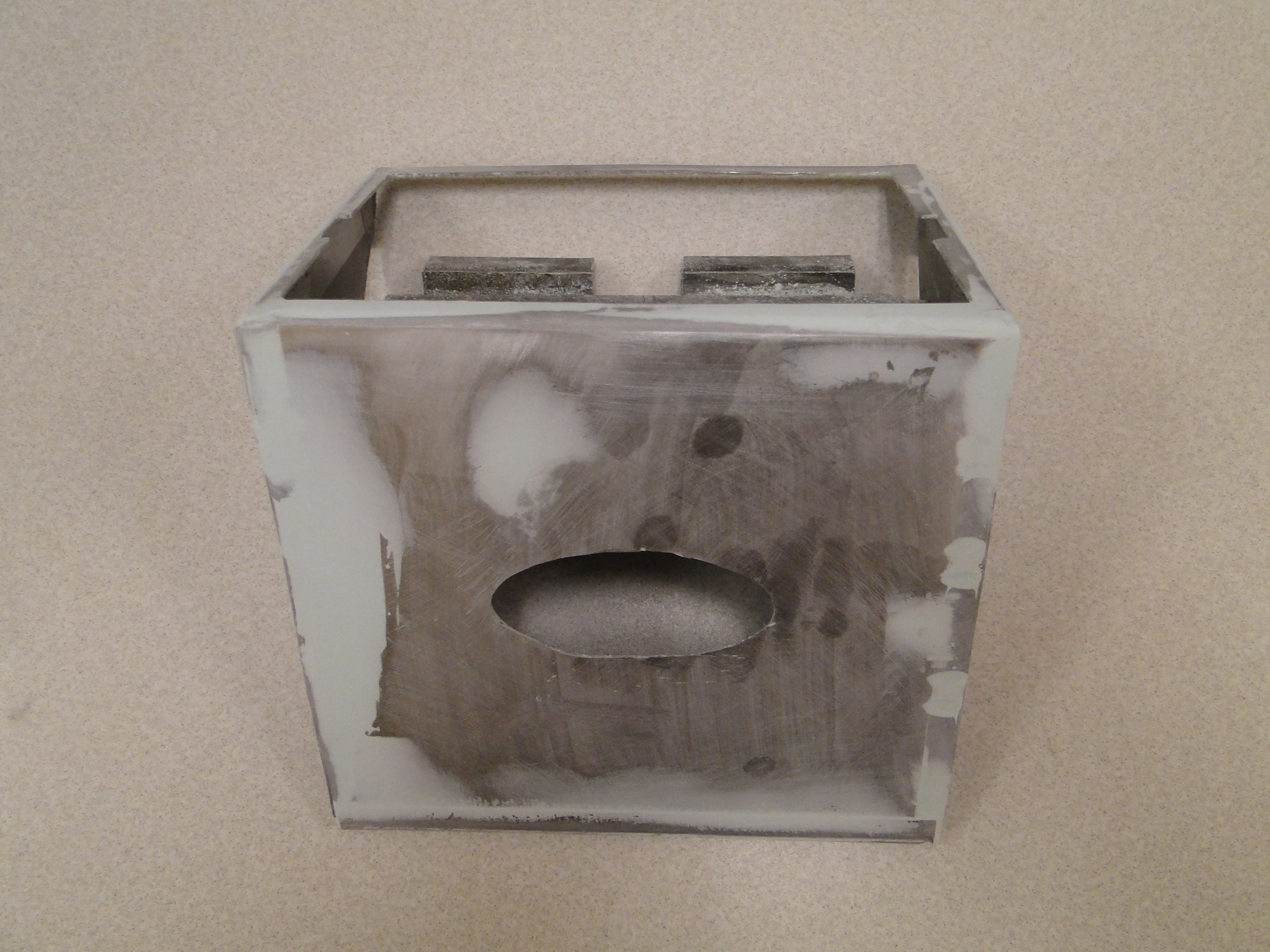
I also need to have room for the dome light. I started with making a mount
for the screen so I could attach it to the headliner molding over top the
speaker hole. Then I cut an oval hole on the bottom of the screen
mounting box for the dome light to fit into.
Click any picture to enlarge.
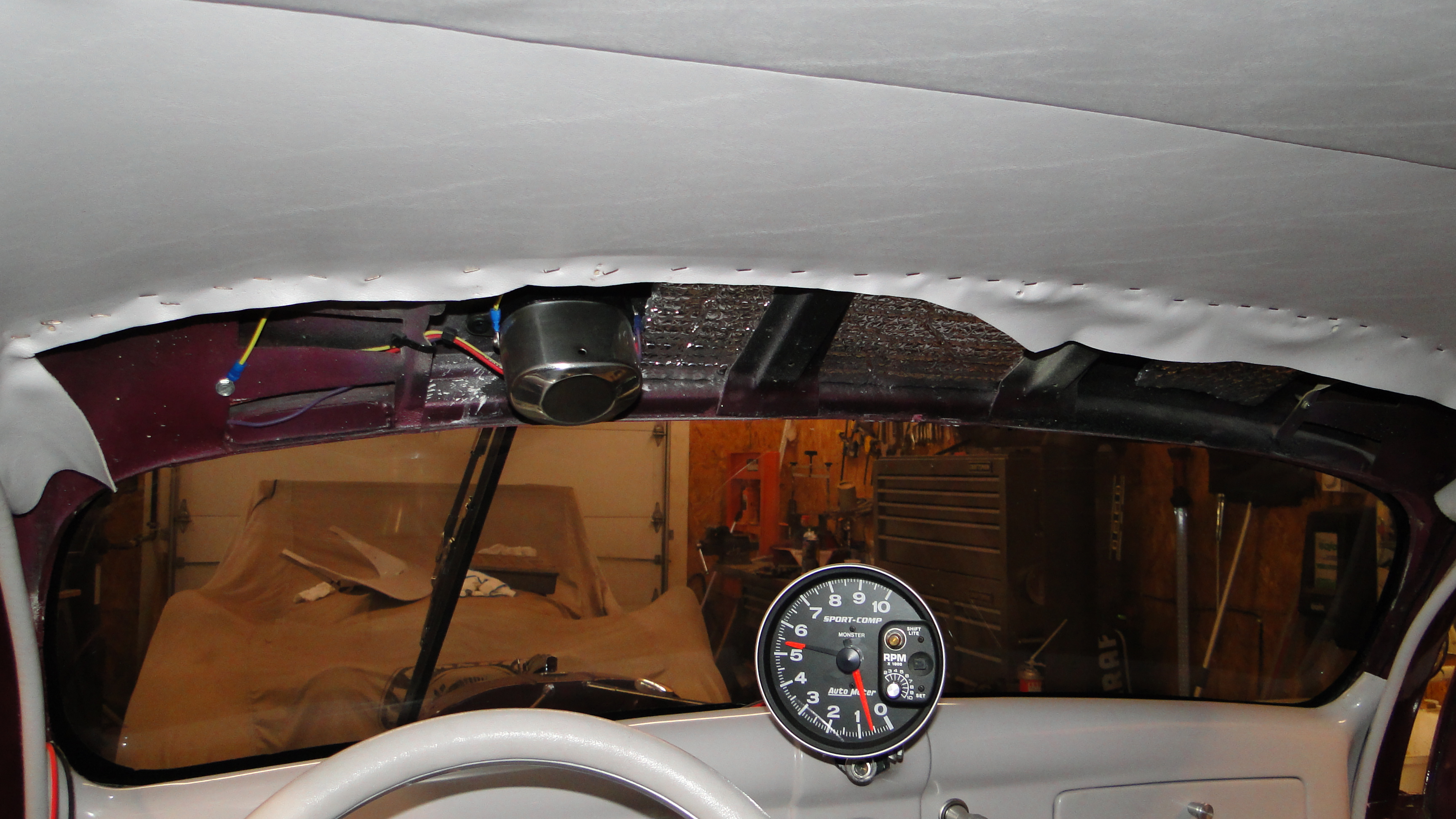
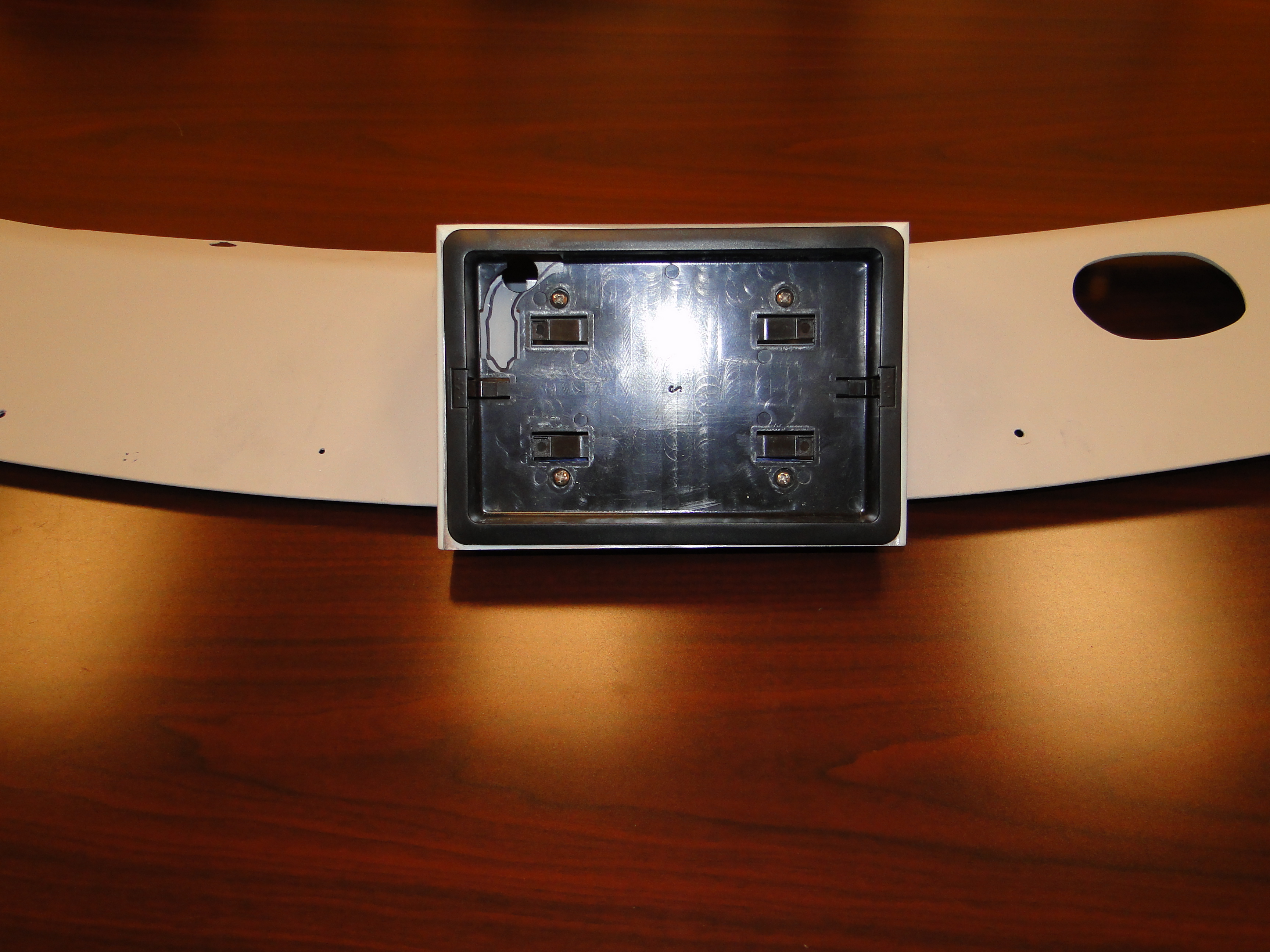
Now I needed to test fit the monitor mount to the headliner molding, and then
mount both of them on the car. Before anymore paint preparation is
done. As you can see everything looked great on the inside, wait not
so fast when I went around the front of the car there was a gap between the
headliner and the garnish molding. This is where the original rear
view mirror mounted and would cover this area up. Now this is an
unexpected problem. I have decided to continue on with disassembling
of the console and start painting anyway. I will deal with this
later.
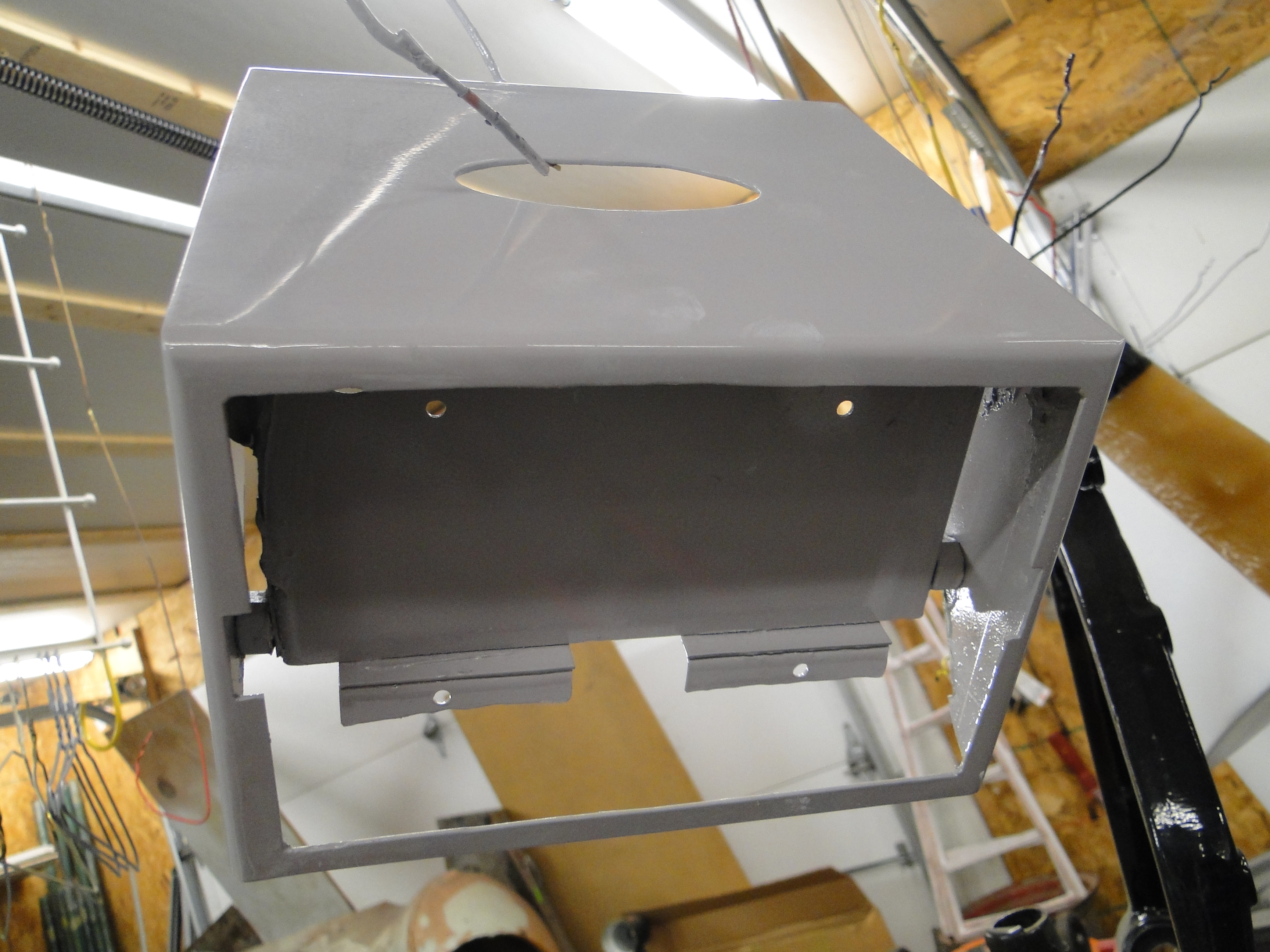
The monitor console came out great, and the garnish moldings look just as
good if not better than I expected. While the paint was drying, I
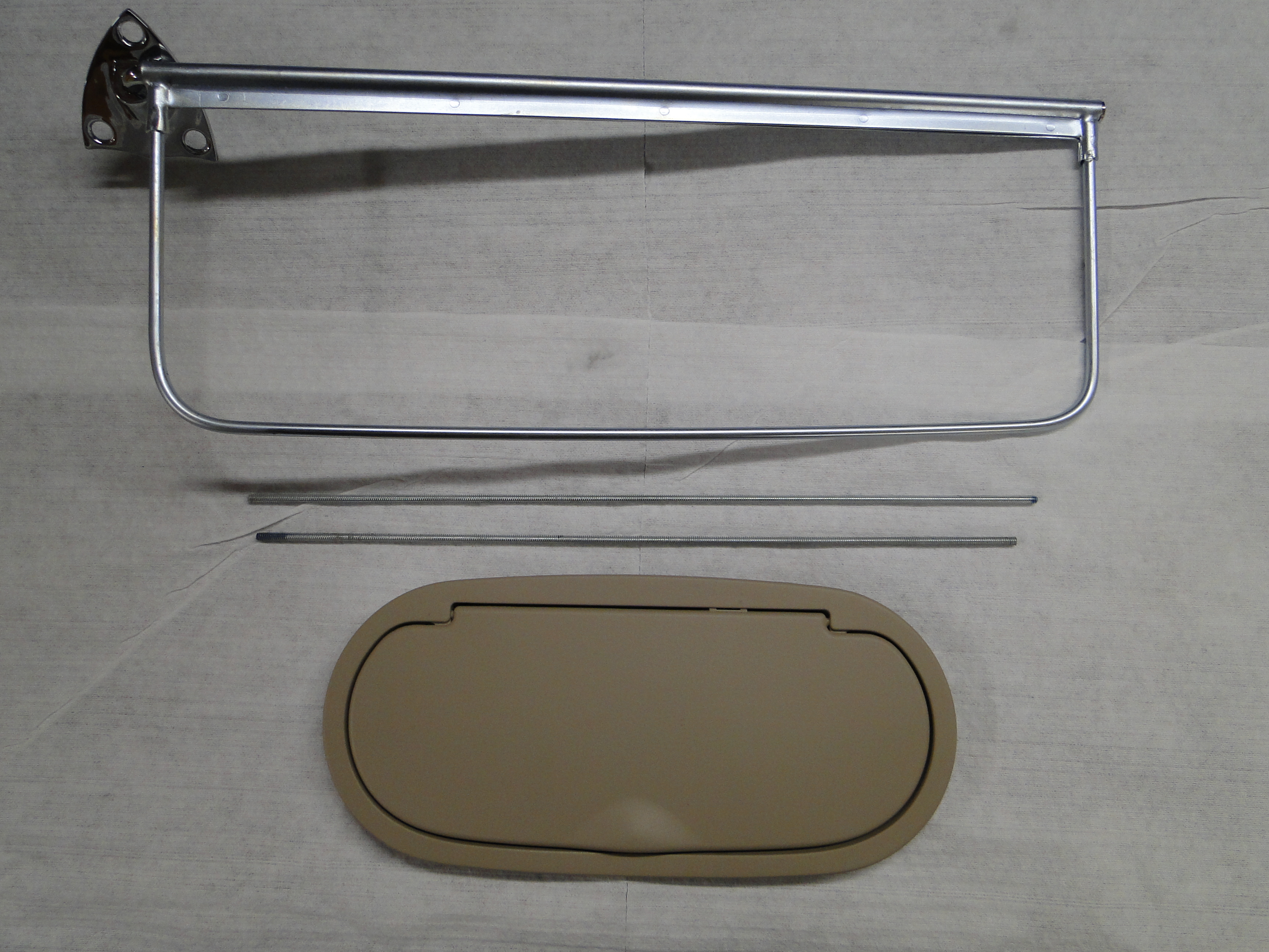
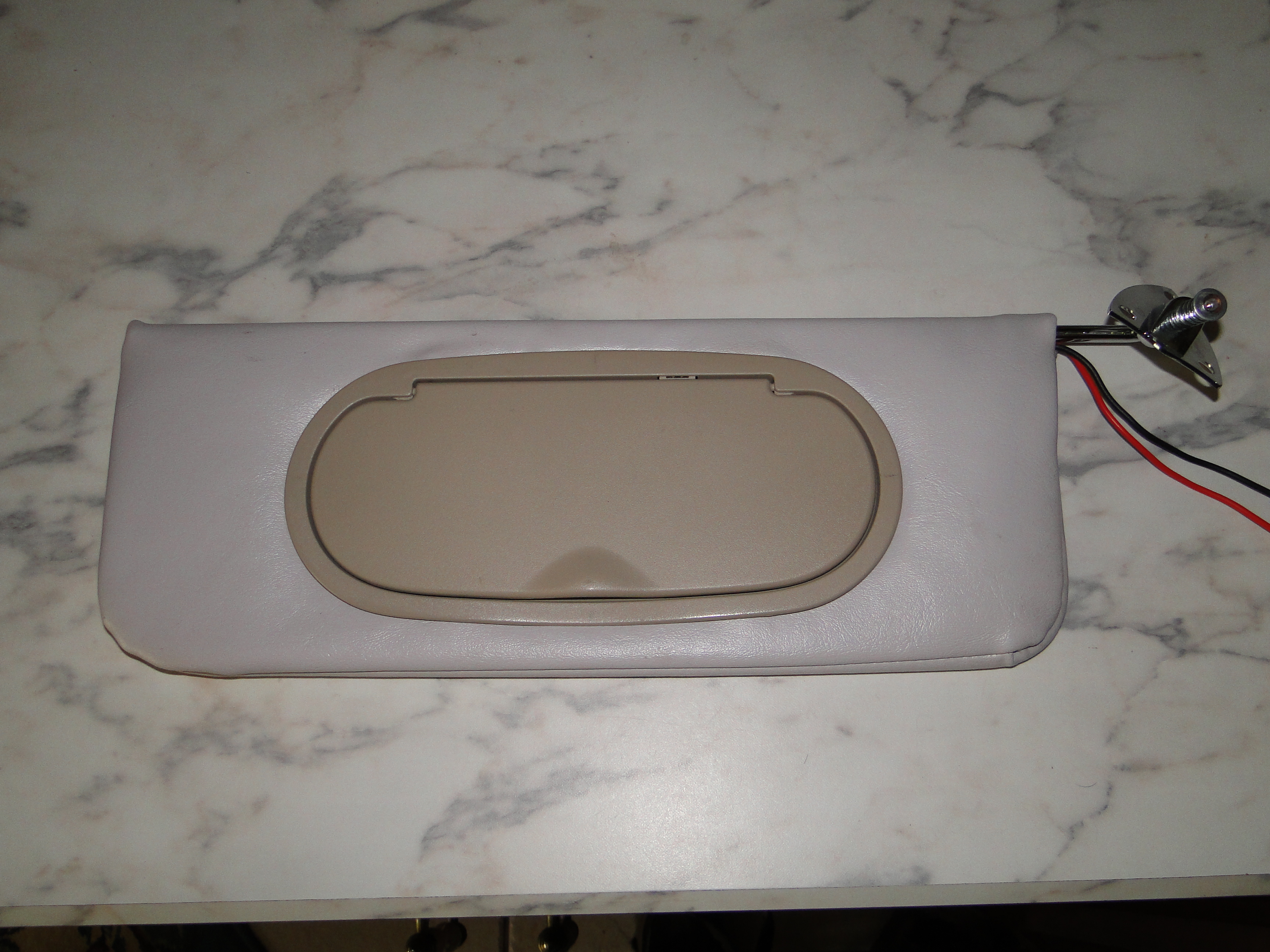
went to work on the reproduction sun visors, that I had purchased.
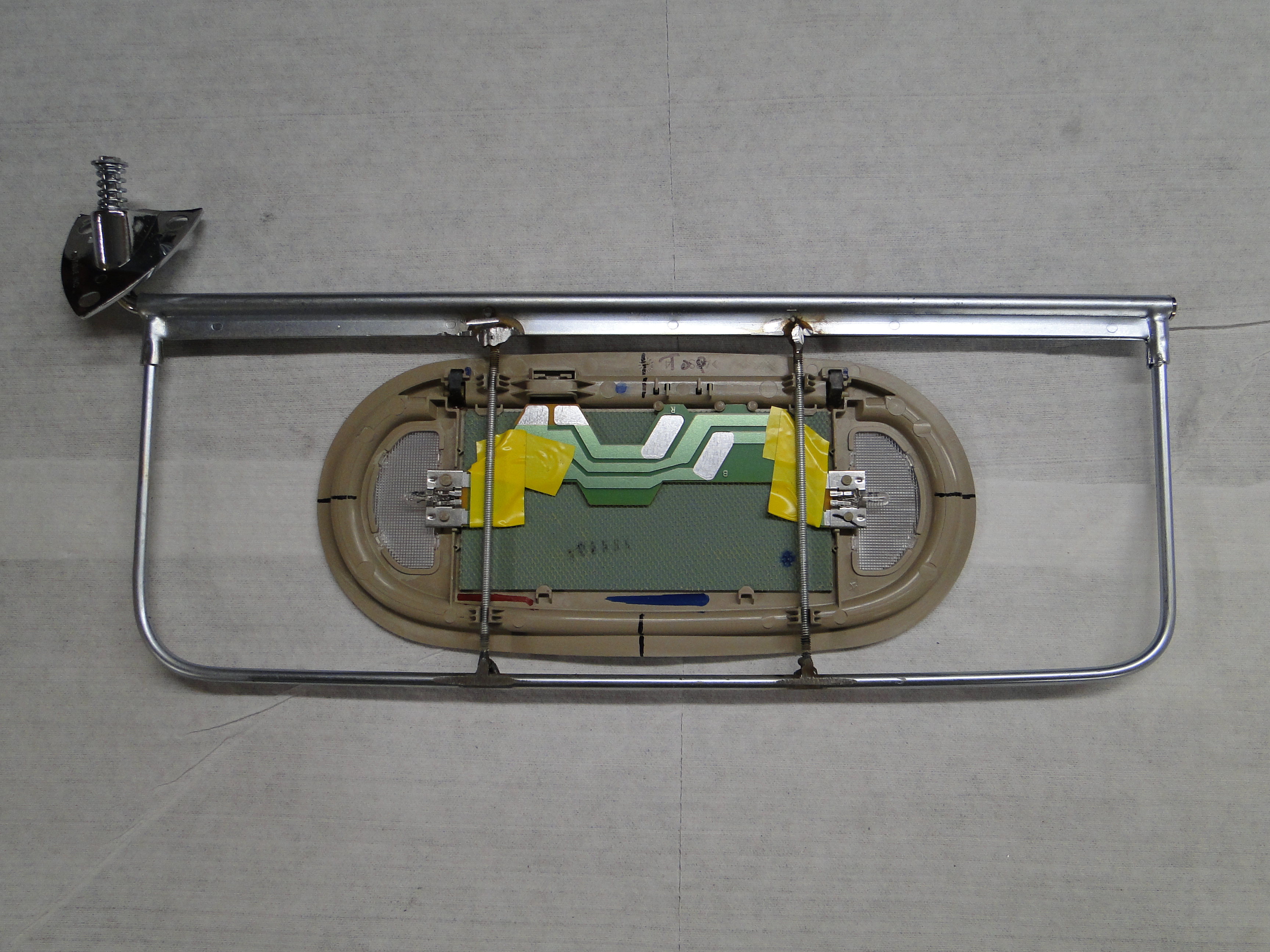
I thought I would get fancy and add a lighted makeup mirror in the
passenger side sun visor. So I purchased an inexpensive GM
lighted makeup mirror and welded two rods for it to clip on to, and then
I had to figure out a way to power the light in the mirror as it is
designed to be powered by contact springs that I don't have.
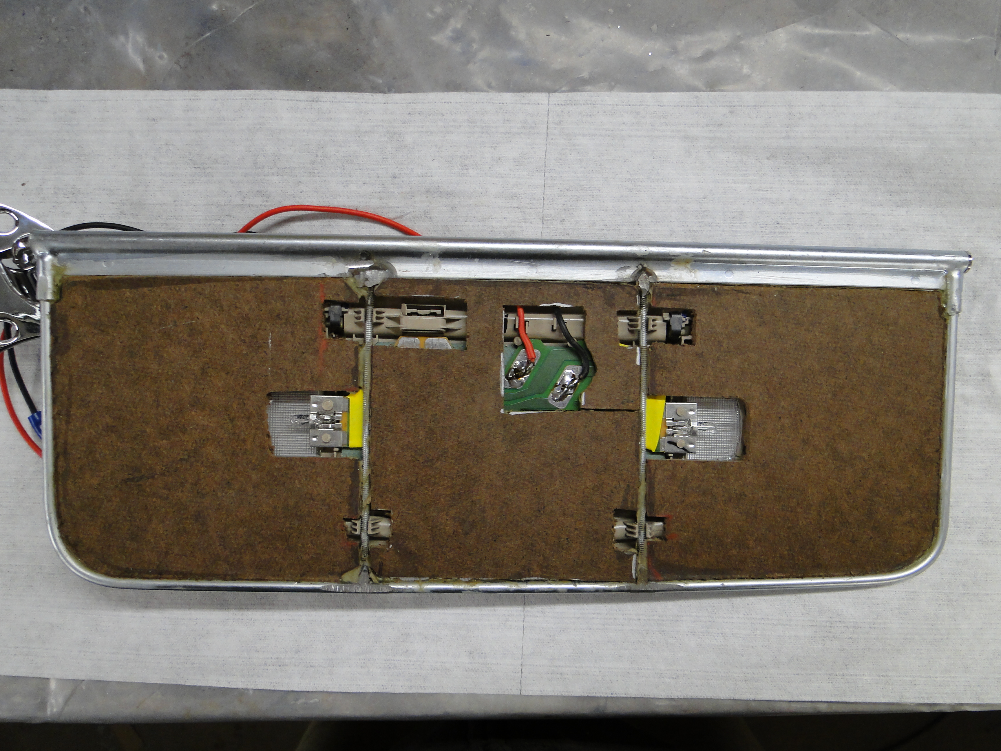
So I soldered both wires directly to the electric contacts, and in
testing it worked just fine.
Click any picture to enlarge.
Click any picture to enlarge.
April
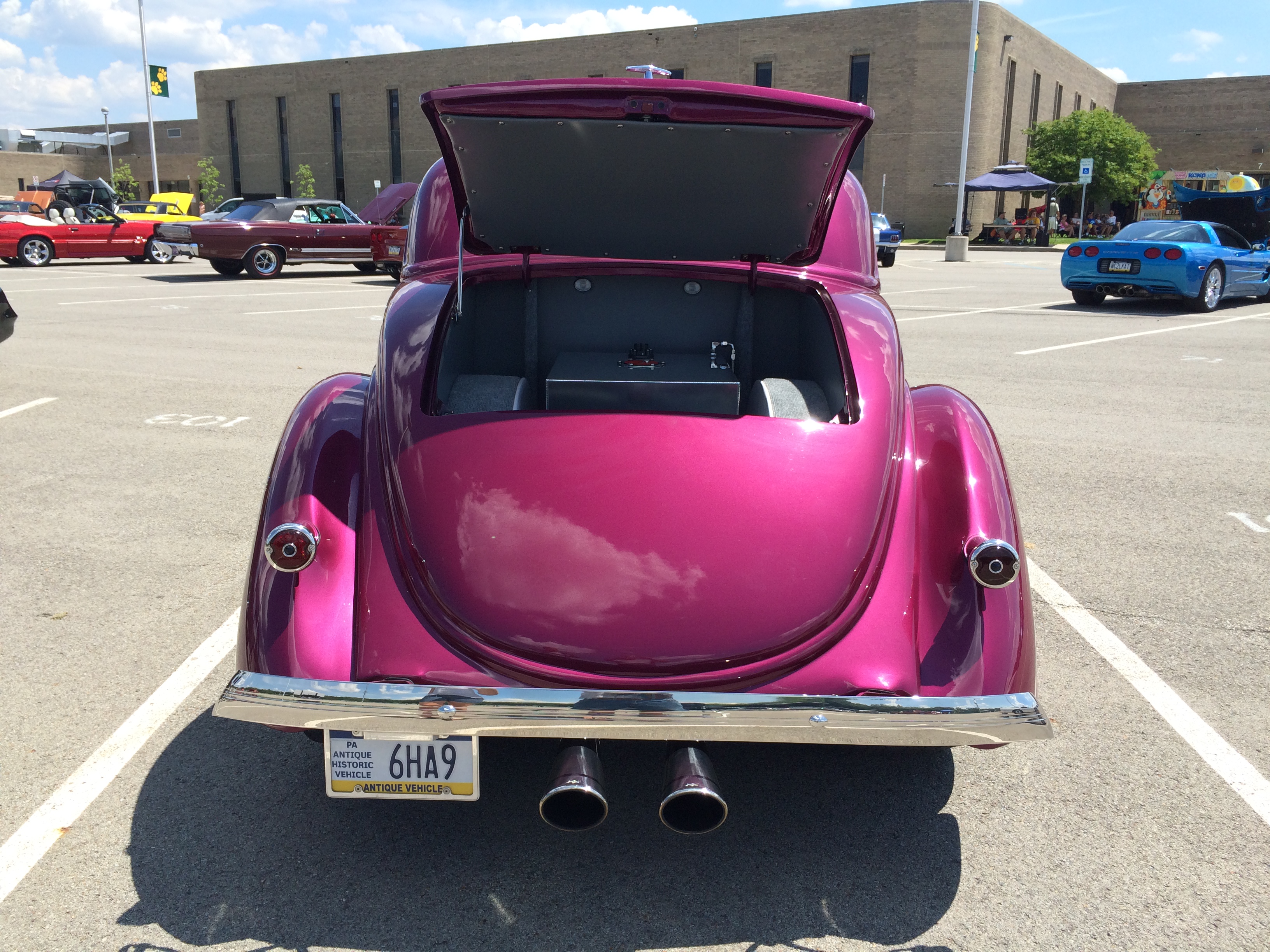
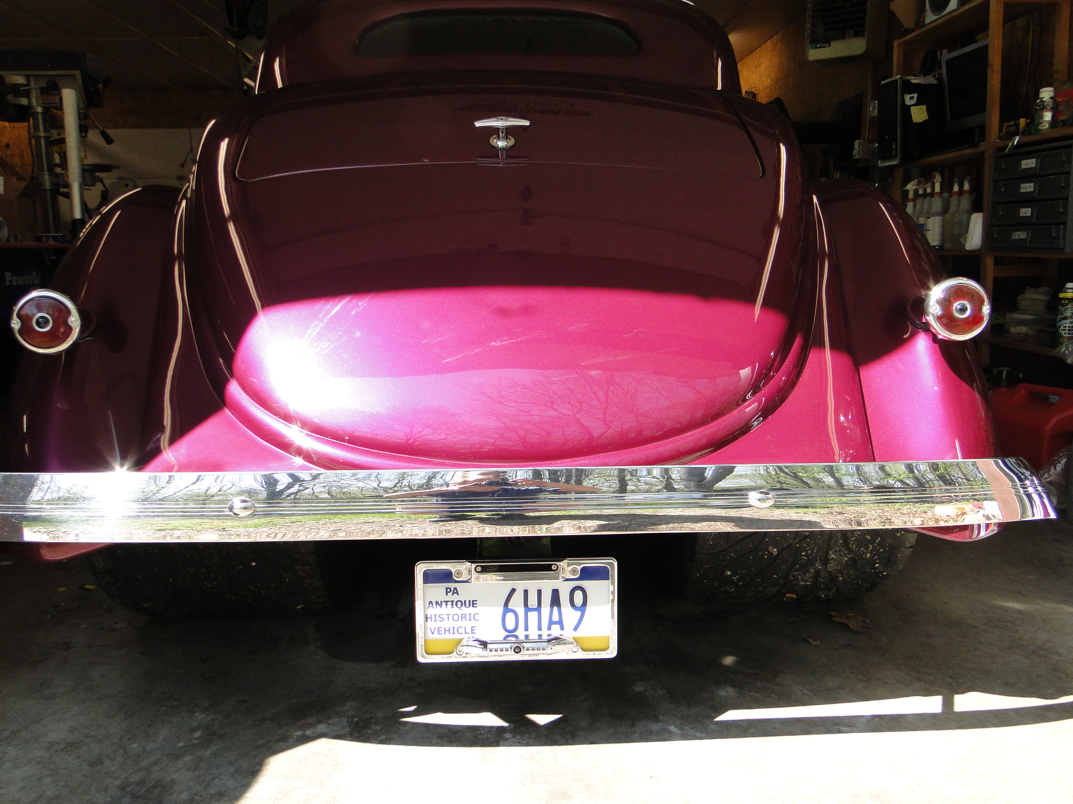
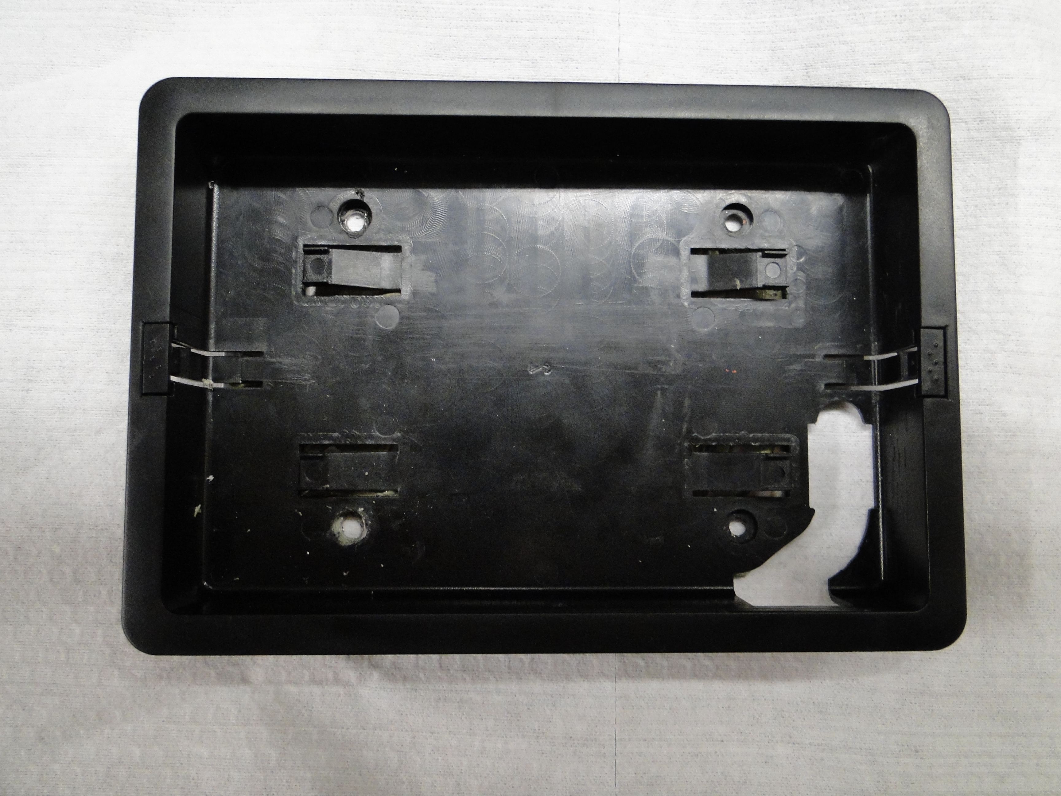
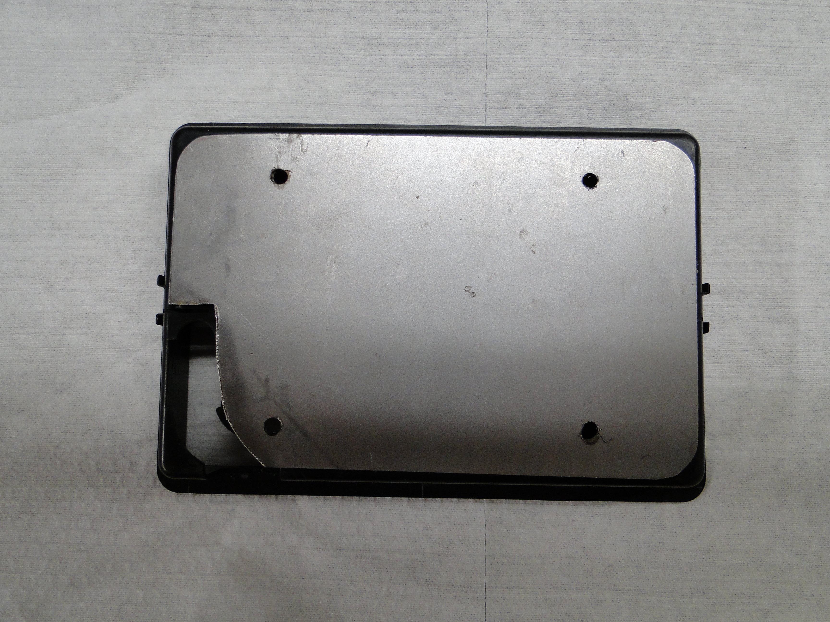
Rear Camera Mount And Wire Installation
My next problem is the camera mounts to the license plate frame,
and I have to move the license plate from the left side of the car to the
middle, in order for the camera to have the correct
orientation. The first issue is I have to make a mounting
bracket and paint the old license plate holder before reinstalling it. Just to
be safe I made one mounting holes larger to allow for final level adjustment.
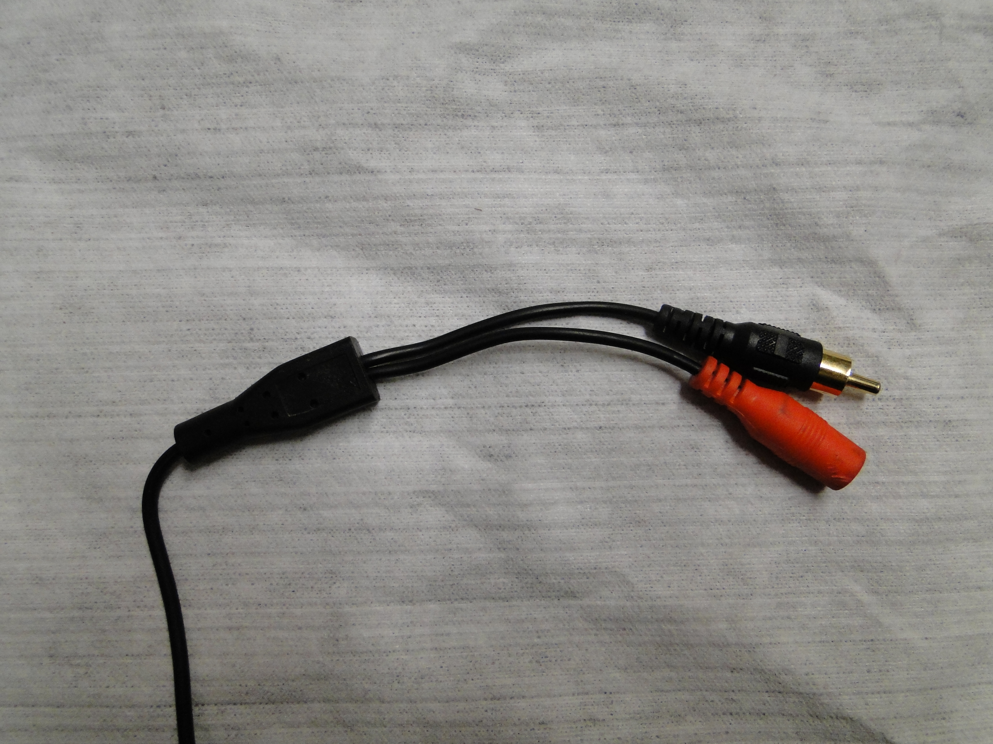
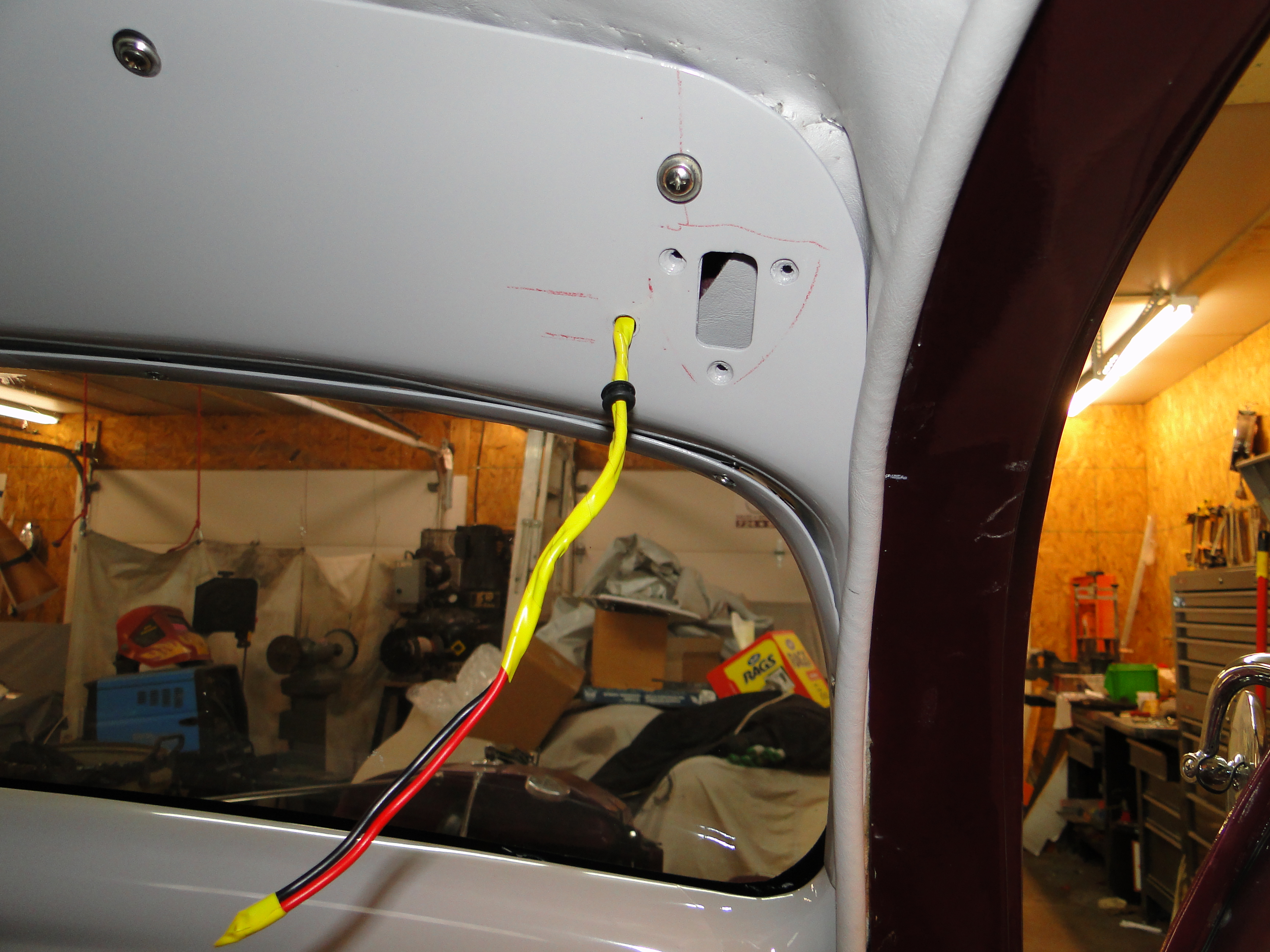
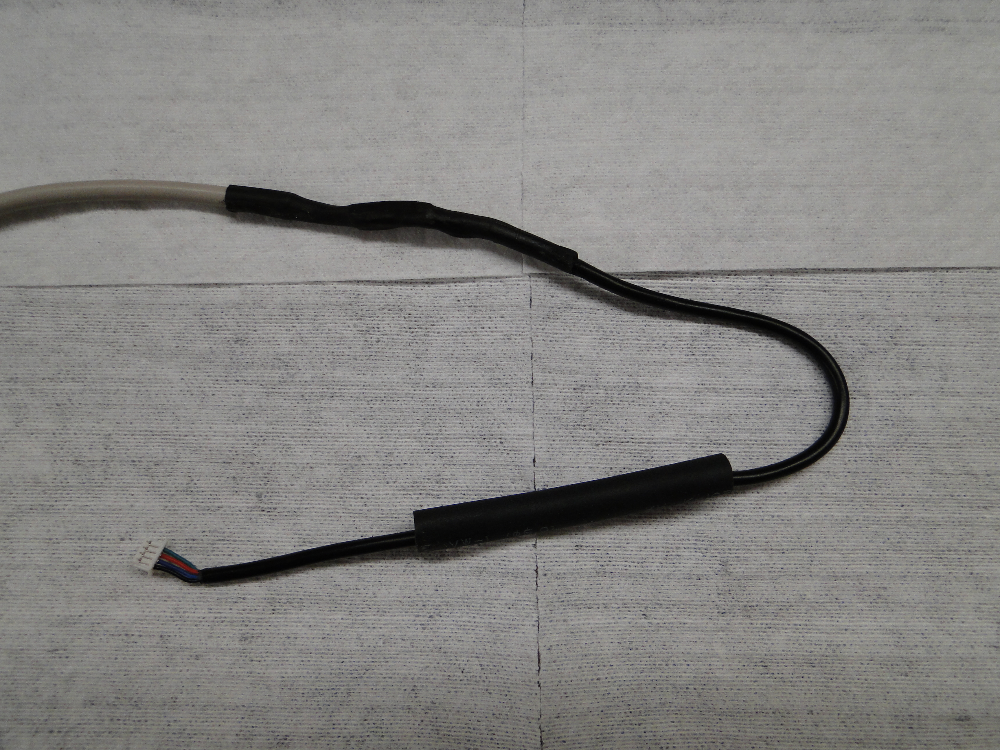
Now for the easy part or so I thought, the camera mounts to the license
plat holder and I have to run the power and signal cables back though the
firewall. Then connect the camera to the monitor wiring harness under the dash. Their is only
one problem the camera cable has a large plastic molded end that will
not fit through any of my firewall holes see first wire photo.
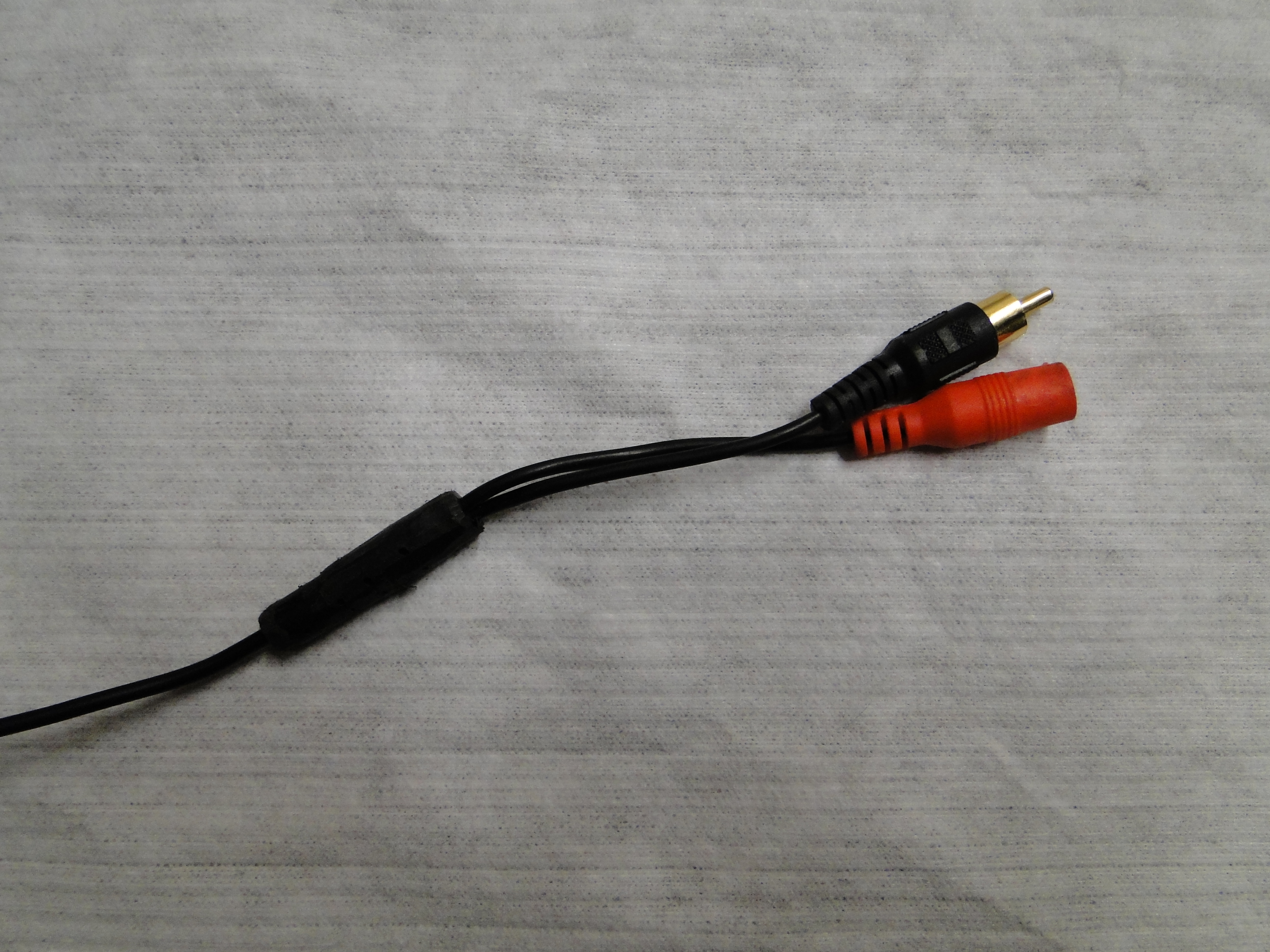
The
plastic molding is more than 3/4 of an inch round, with no other option I
had to carefully grinded the plastic away with out damaging the wires
inside,
so it would fit though the firewall hole. See second wire photo
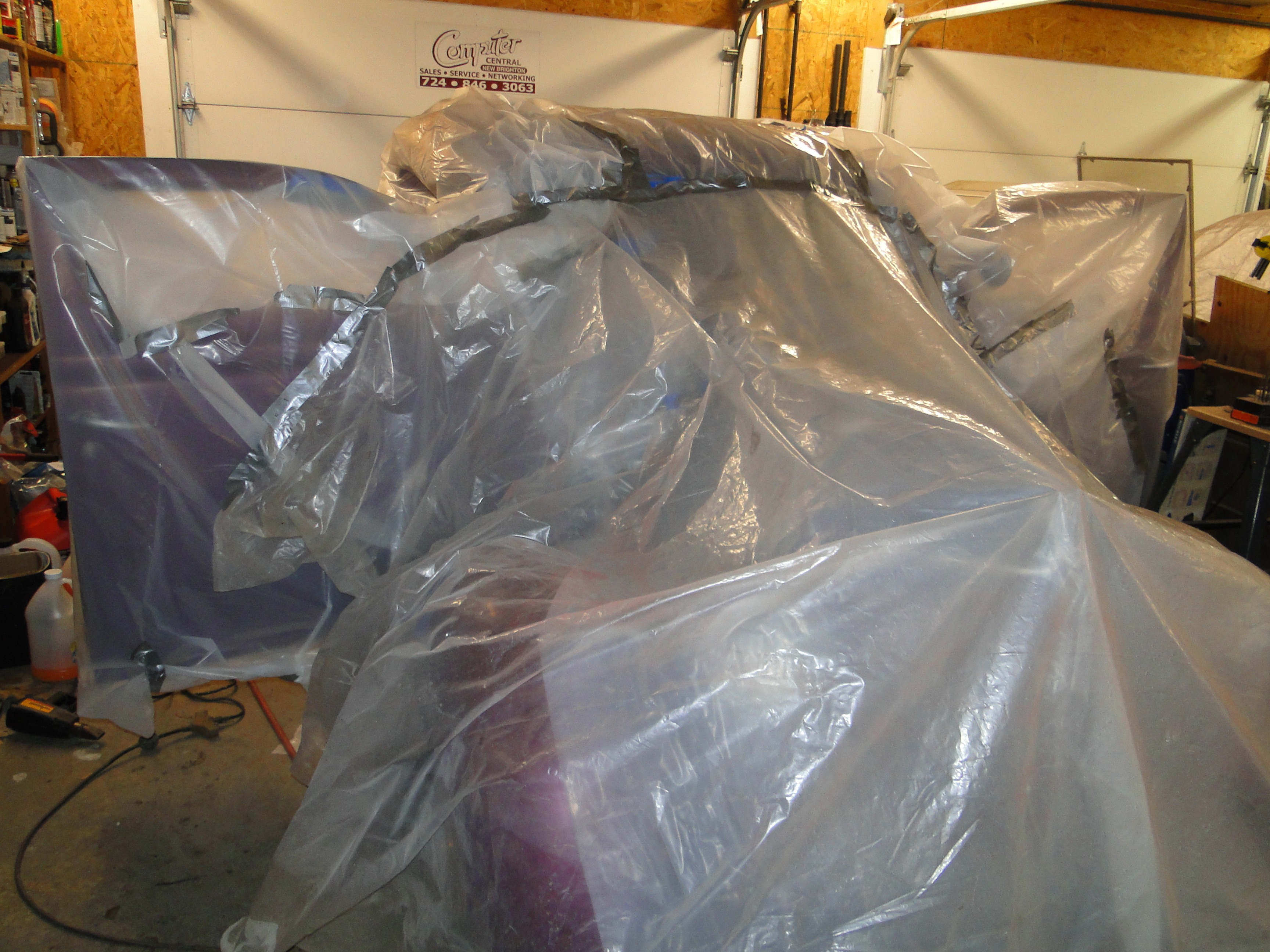
Dash Paint Repair
During my test fit work on the garnish moldings, I accidently scratched
the dash where the two metal parts are connected. The paint repair
had to be completed before I could mount the new headliner and console
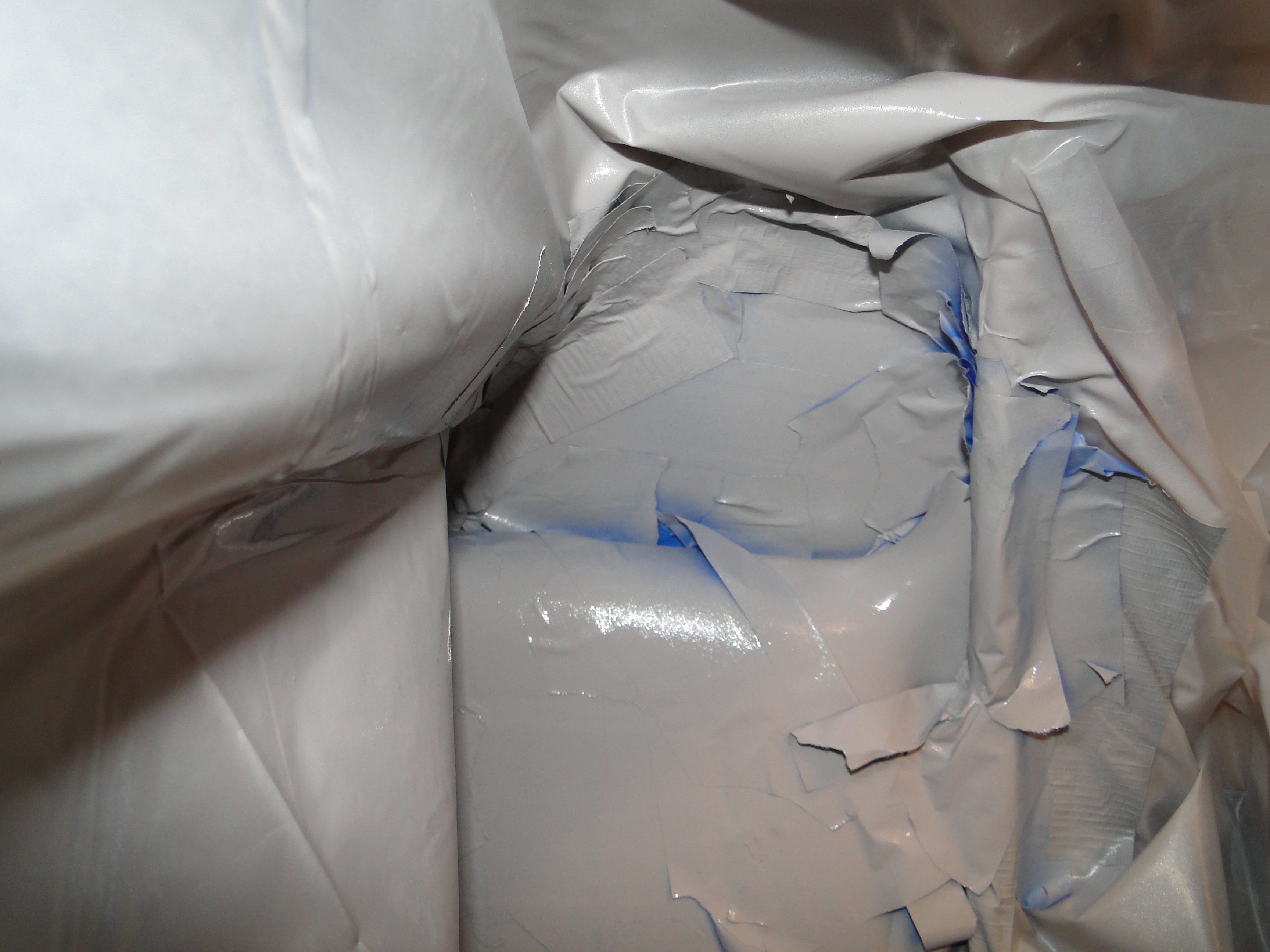
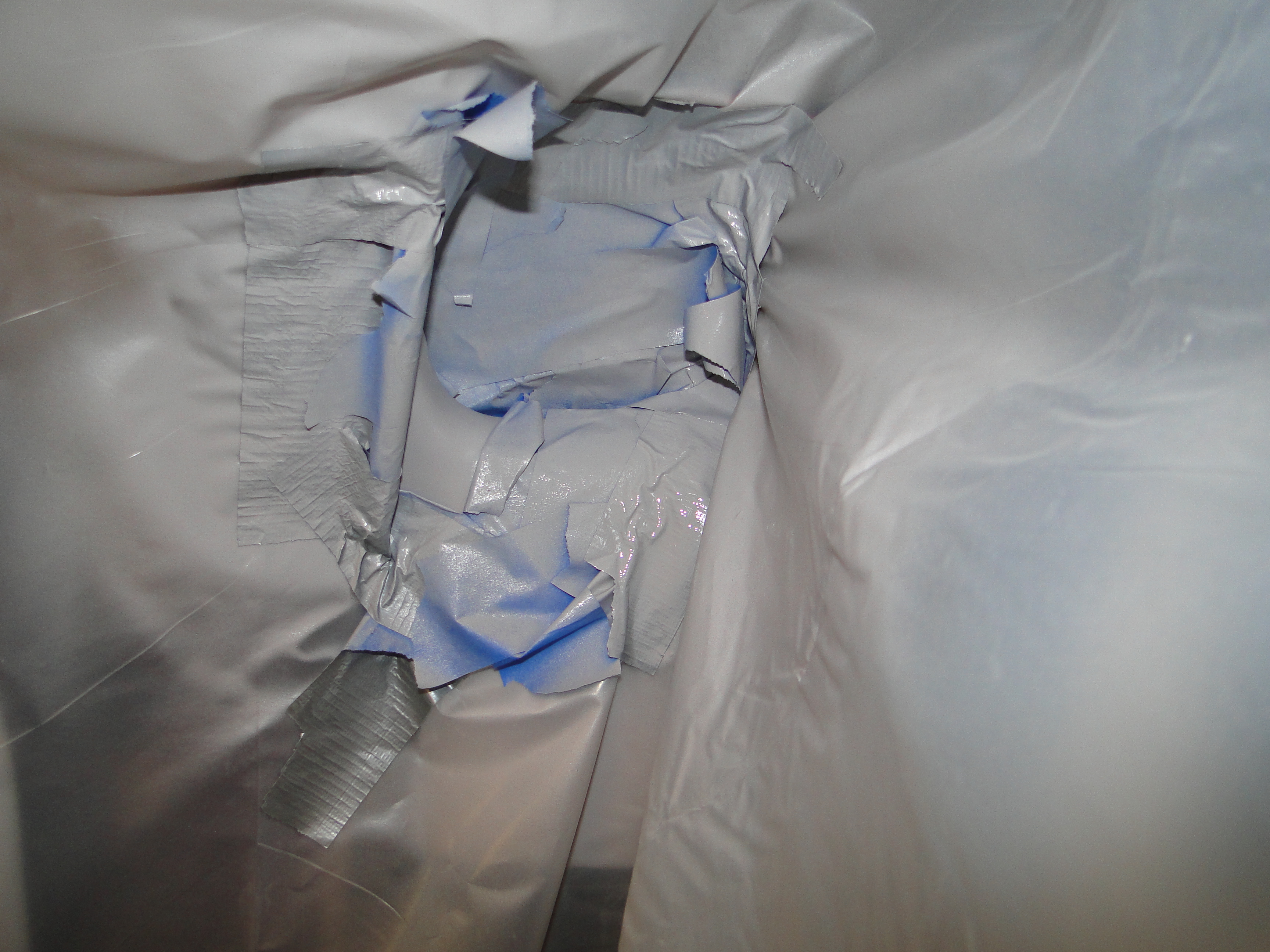
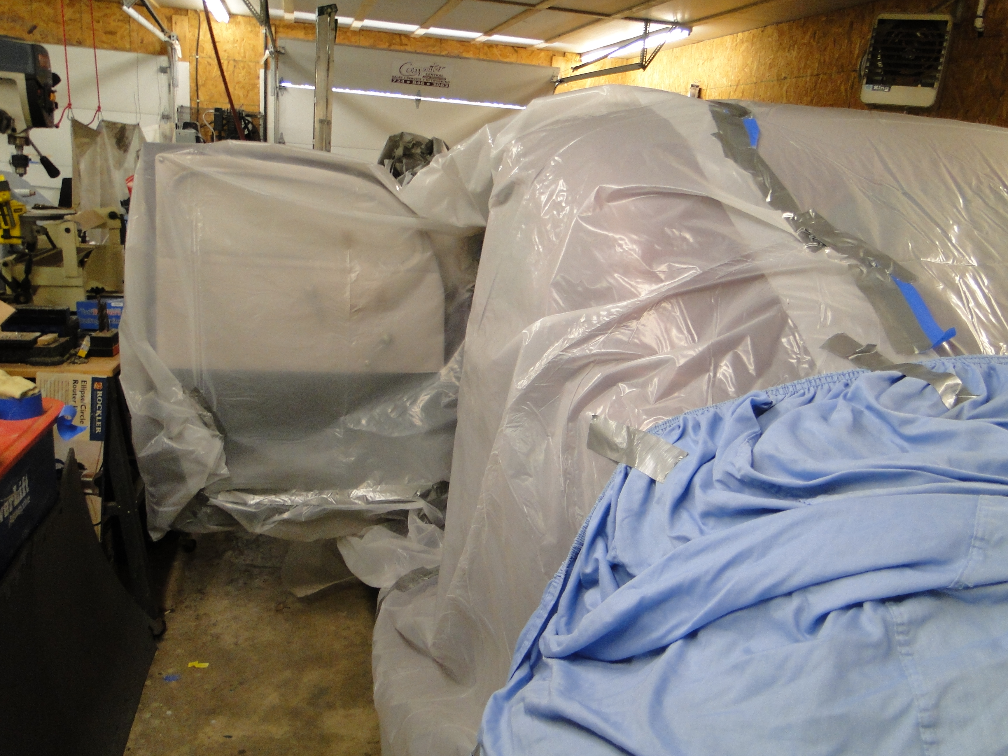
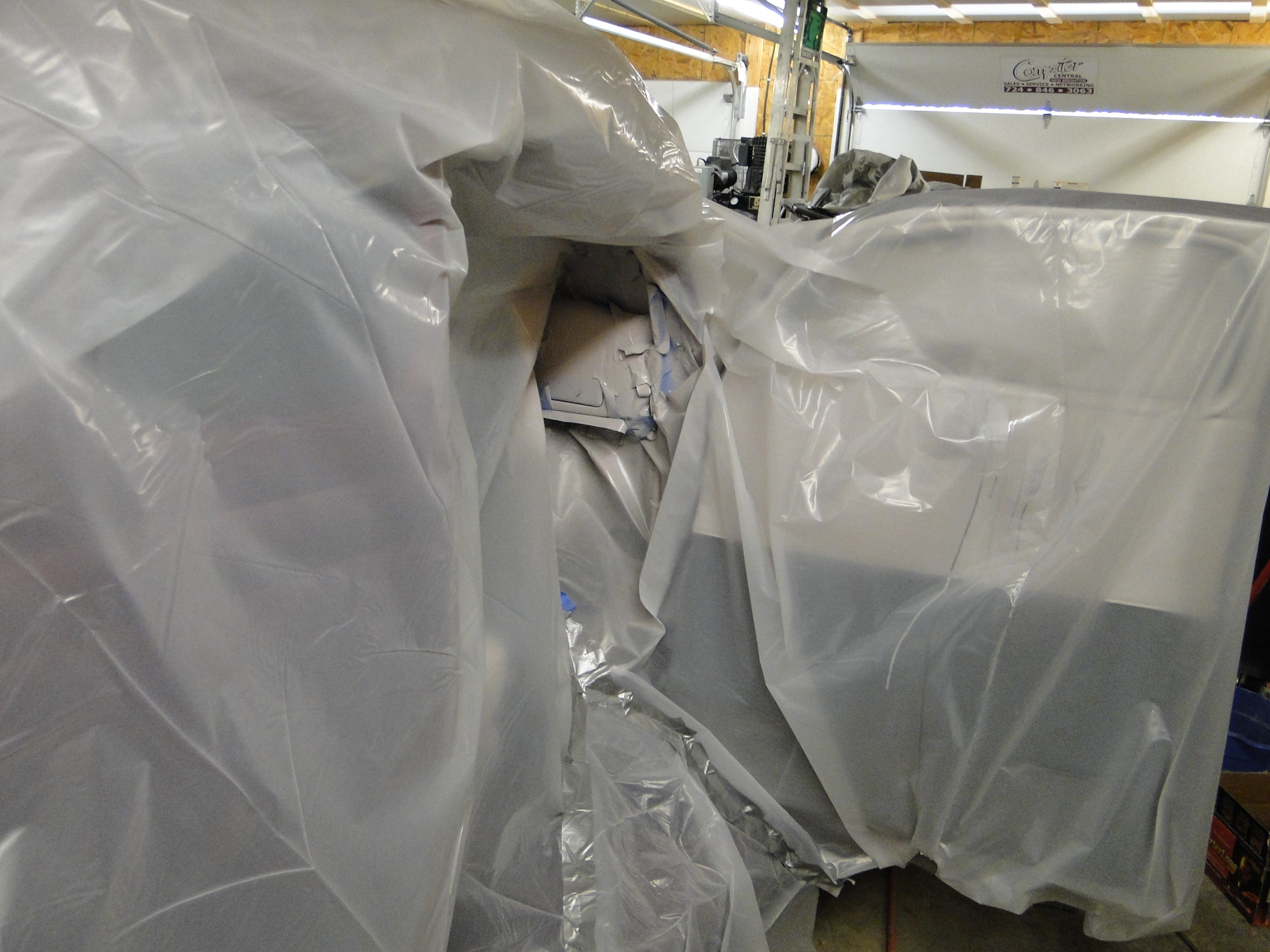
in the car. Well this was a
major ordeal to fix as I had to literally cover the entire car with
plastic to protect
it from the overspray when I touched up the paint on both sides of the
dash.
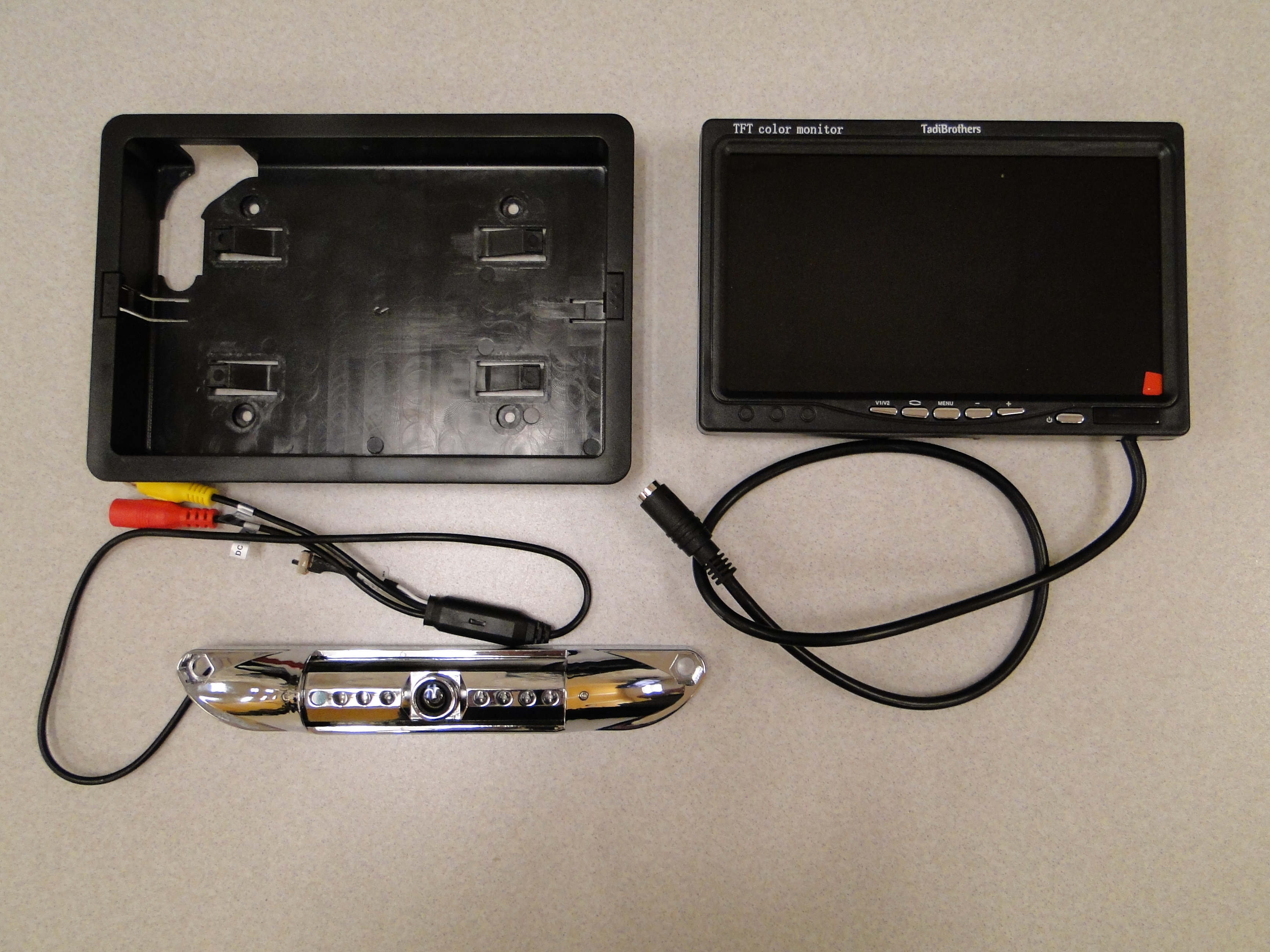
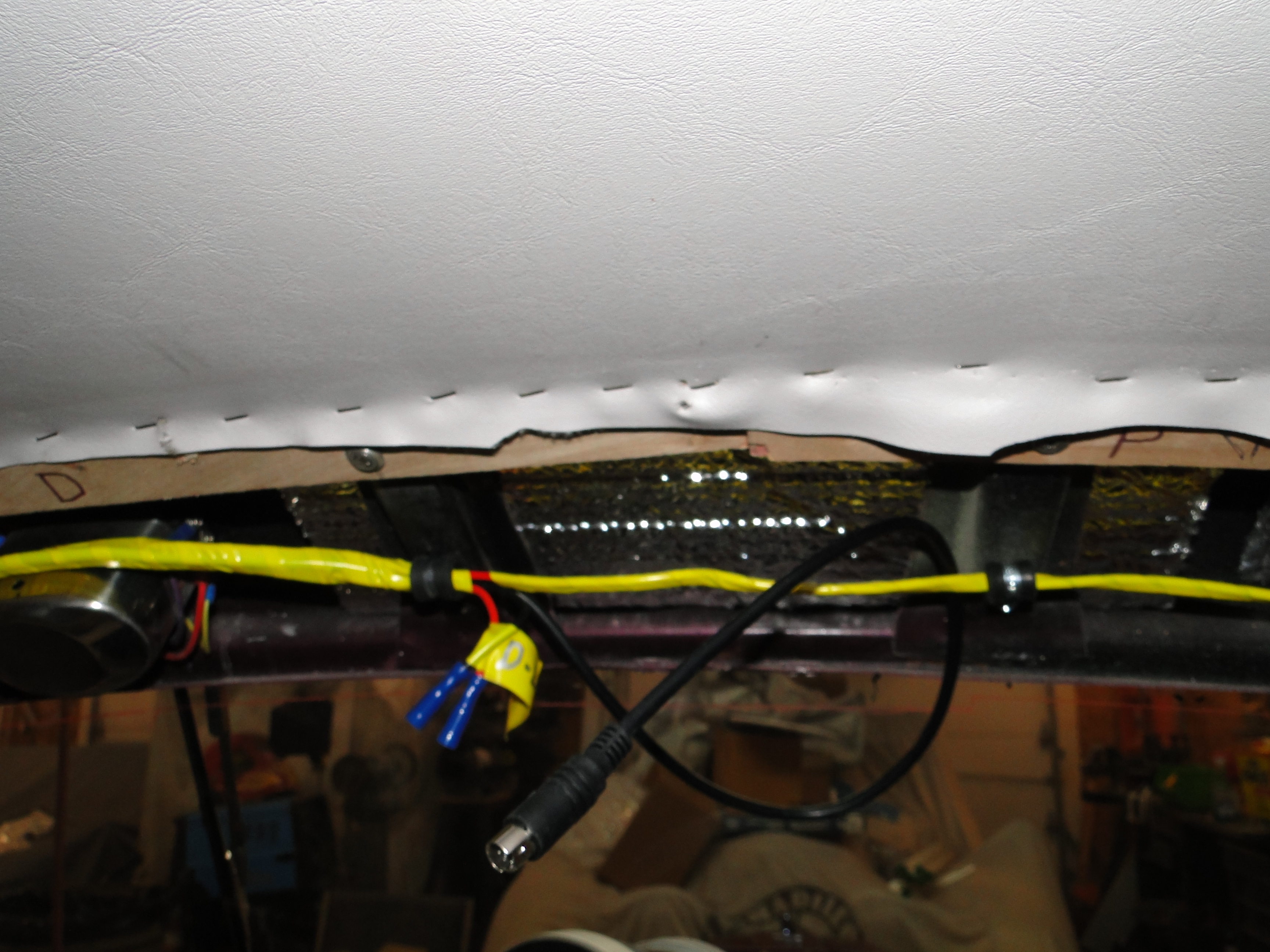
Camera And Monitor Installation Part 1
Now that the dash paint repair is complete I can start the camera,
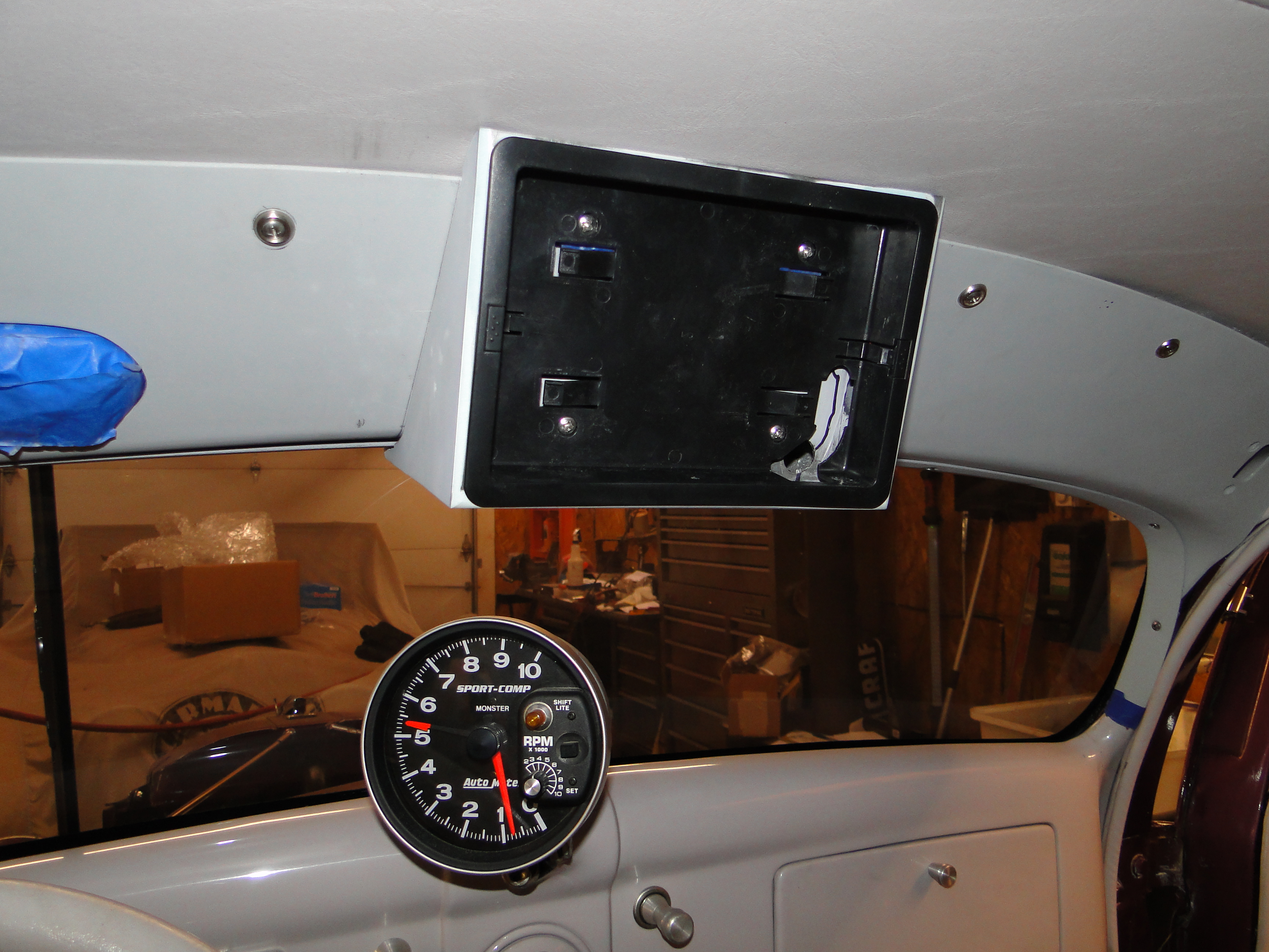
console and wiring installation. The first problem I ran in to was
the plastic monitor mount that holds the monitor in the console failed
where the mounting screws pass though it. I mean I may have
over tightened them a little bit but the screws went right though the
plastic. At this point I
needed to reinforce the back of the monitor mount with a piece of sheet
metal. I glued it to the plastic monitor mount so the screws
would not pull through. I now needed to run wire for the
dome light, sun visor makeup mirror, and of course the monitor.
In order to prevent the dash from getting scratched again I added a
rubber gasket to go between the dash and the garnish molding. See last
photo.
The first power on test of the HD digital rearview mirror was not completely
successful, it would seem I mounted the rear camera upside down. Once I corrected the
camera orientation I was good to go. Then I was thinking, this HD monitor has a second
video input port for another device, and what could I use that for?
It would be a shame to waste the second video input port. I wondered if I
could connect my IPhone to it?
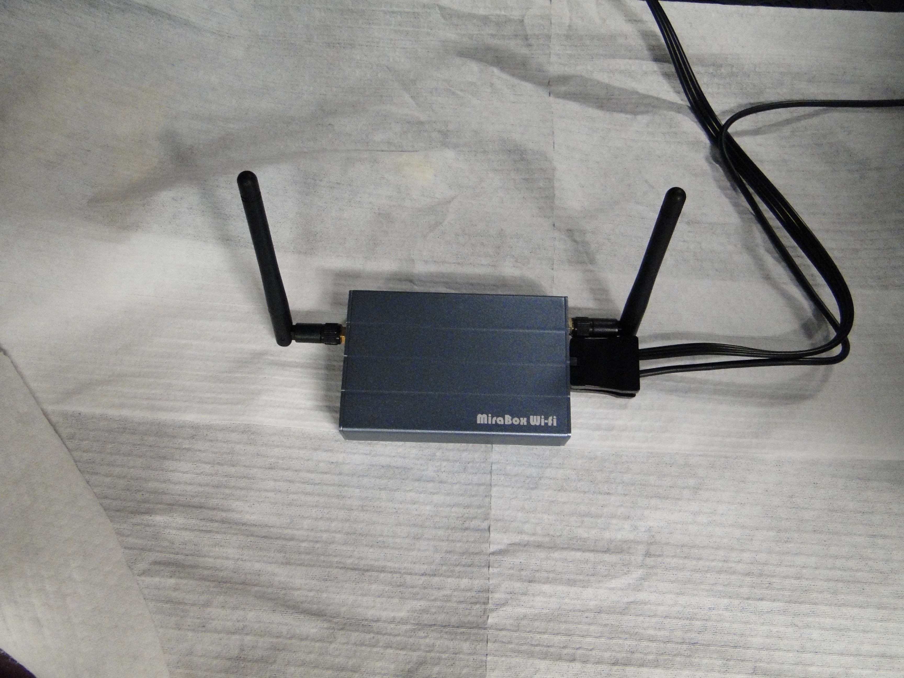
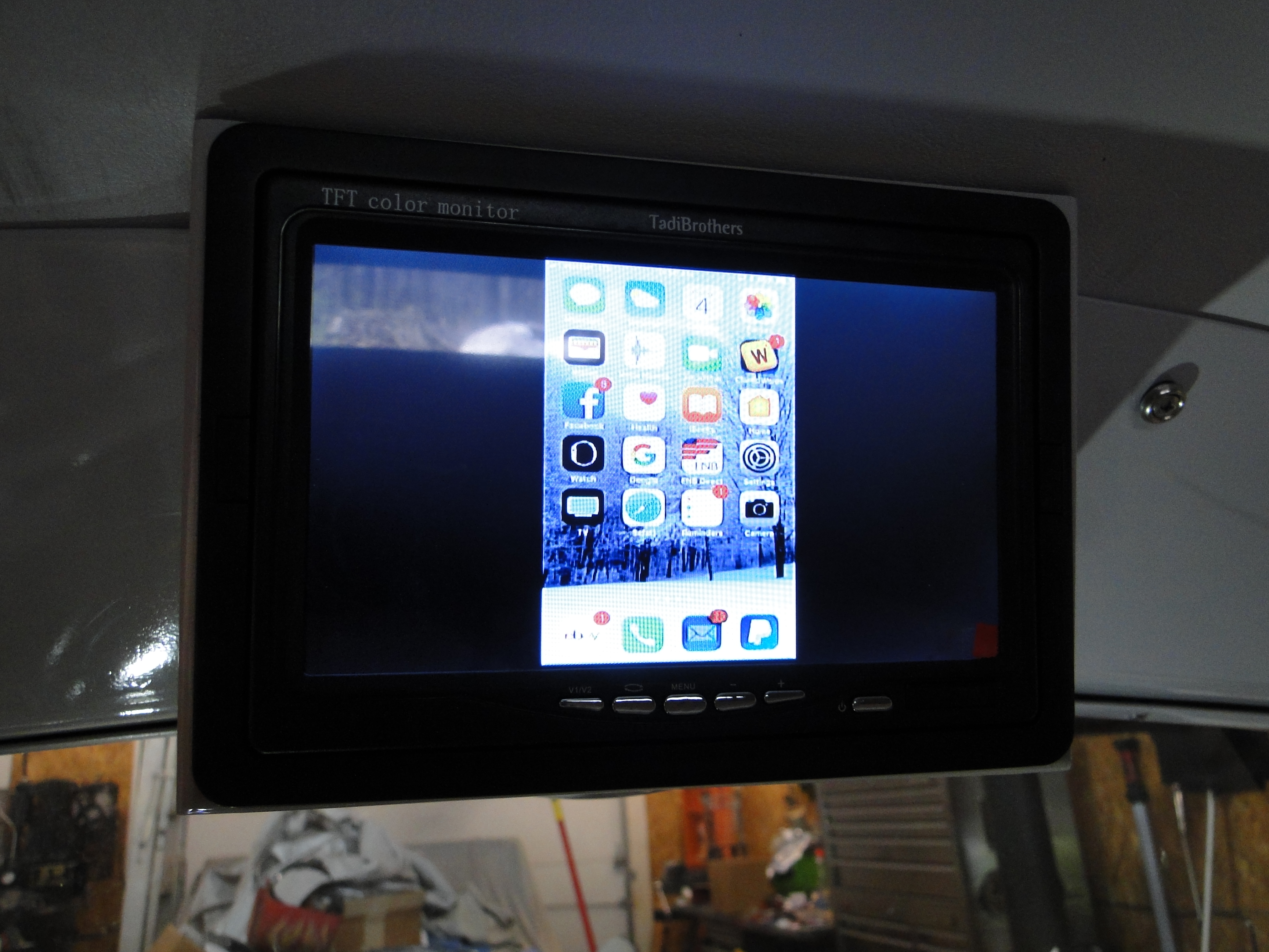
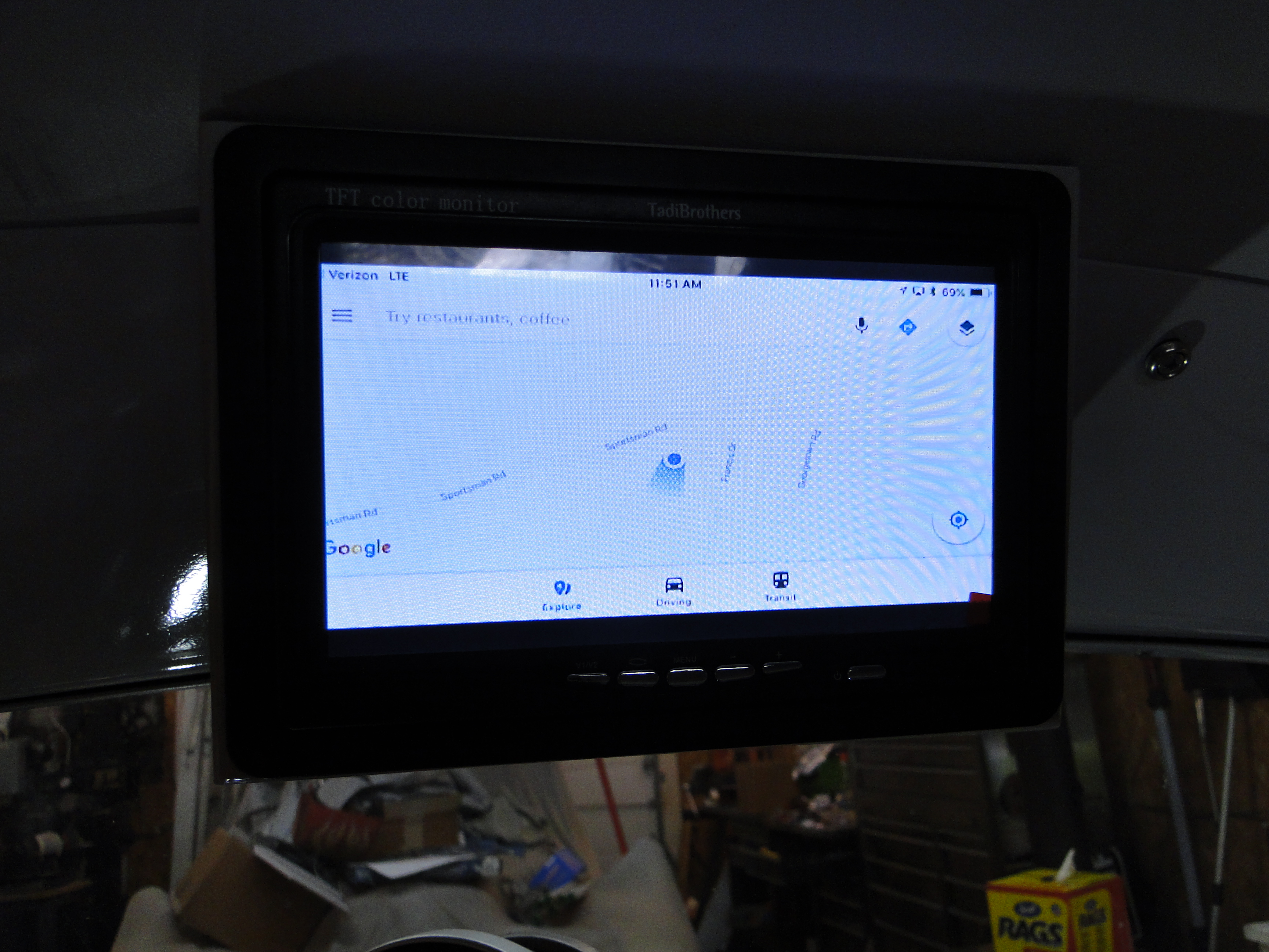
So I did some R&D and came up
with a wireless based system that would display my IPhone to my HD monitor.
This will allow me to show my phone screen, GPS, movies, videos, just about anything
from my phone will be displayed on the overhead HD monitor.
After I connected the MiraBox device, the second video input screen
worked fine, but now we have a sound issue now, I could barely hear the
music on my speakers. That means I need a amplifier to allow
me to hear the music at a decent level. Great so I purchase
an Alpine AMP and now we have sound, actually way to much sound you see
the sound volume is controlled by my Iphone that has to be synced up
before it can take control of the sound volume. What I end
up with is the sound starts out at full blast until I can turn it down
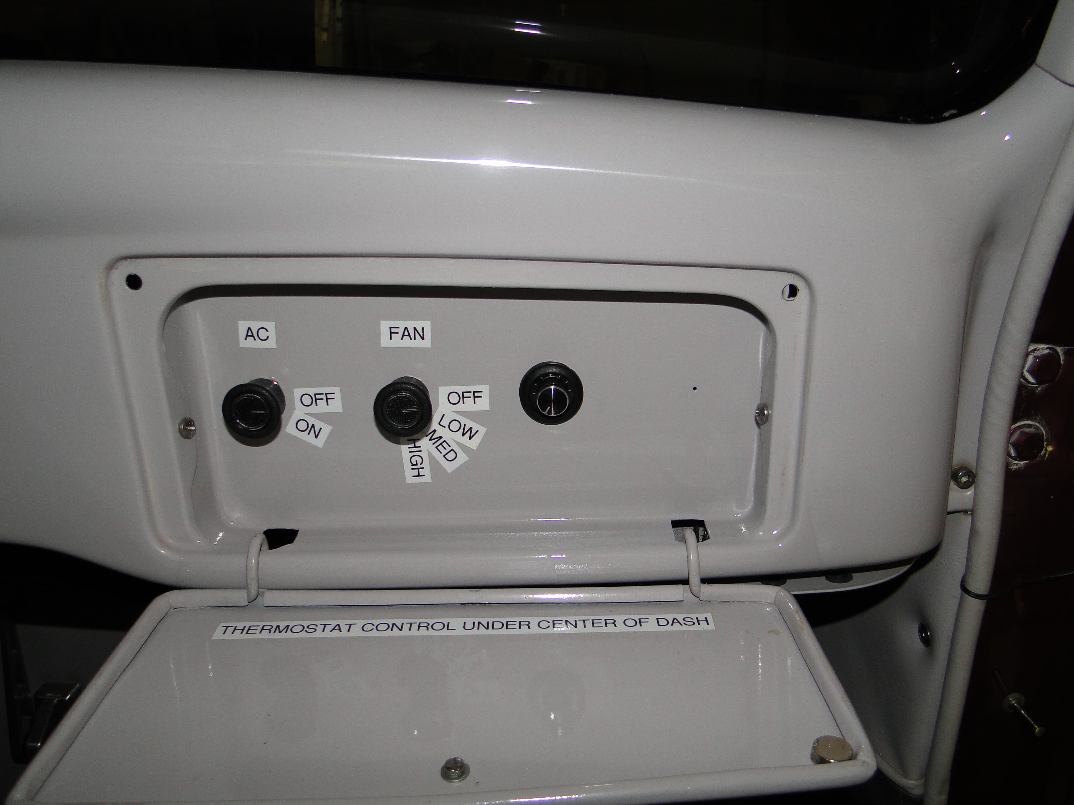
with my Iphone, this is not good at all. So I looked for a
volume control that I could install between the AMP and the MiraBox device to control the volume then I mounted it in the glove box
where we could have easy access to it.
Click any picture to enlarge.
Click any picture to enlarge.
Click any picture to enlarge.
Click any picture to enlarge.
May
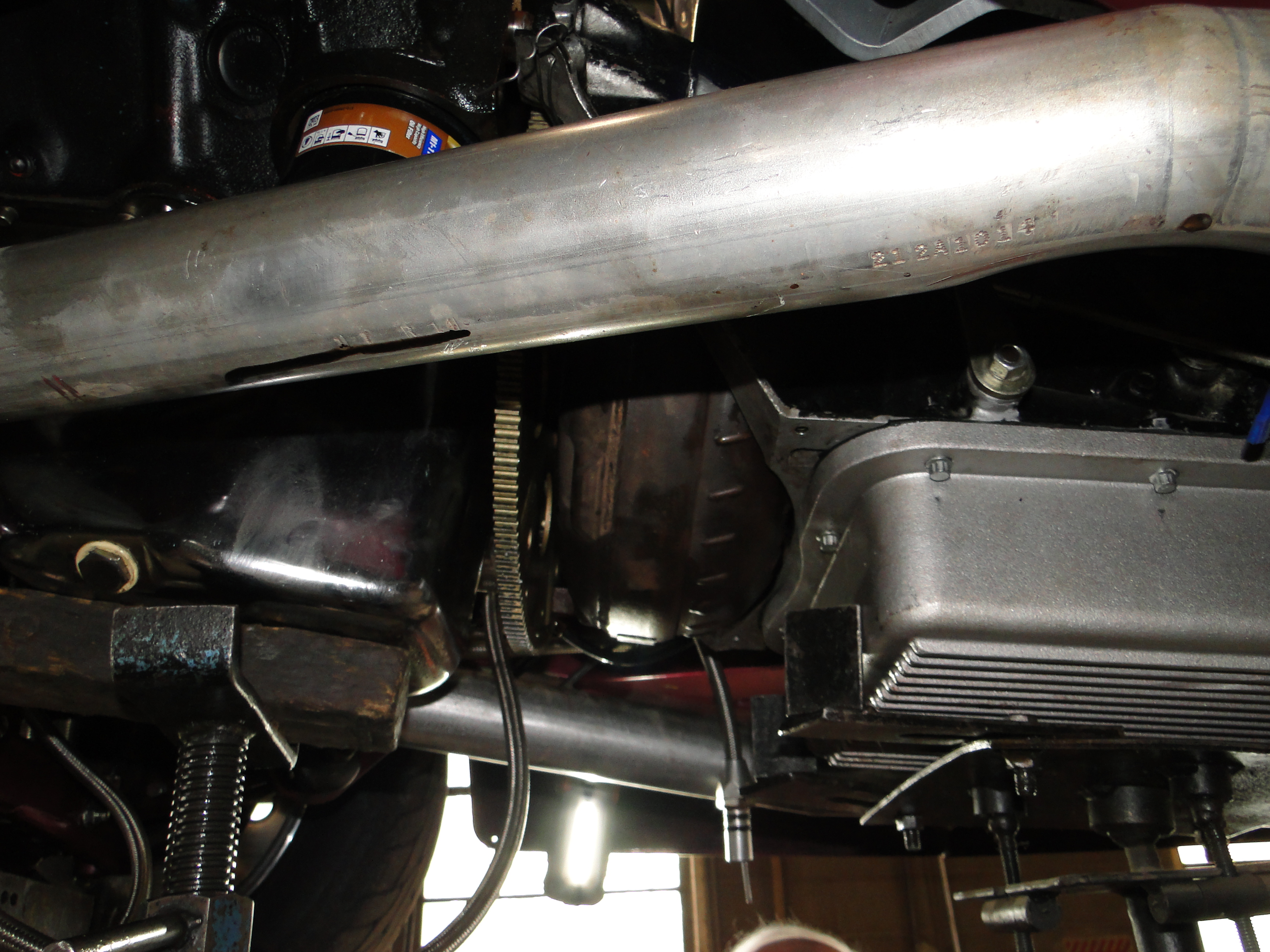
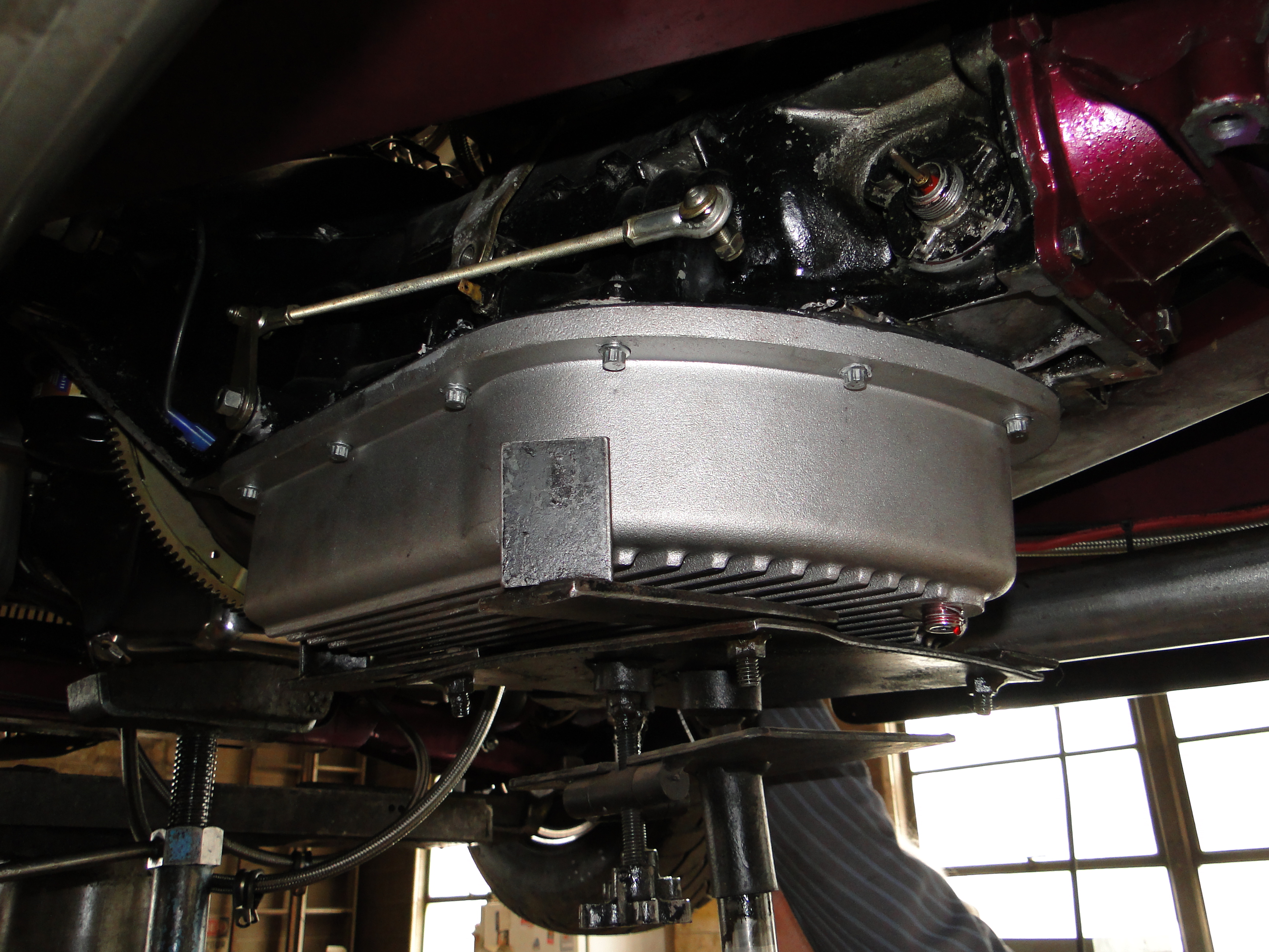
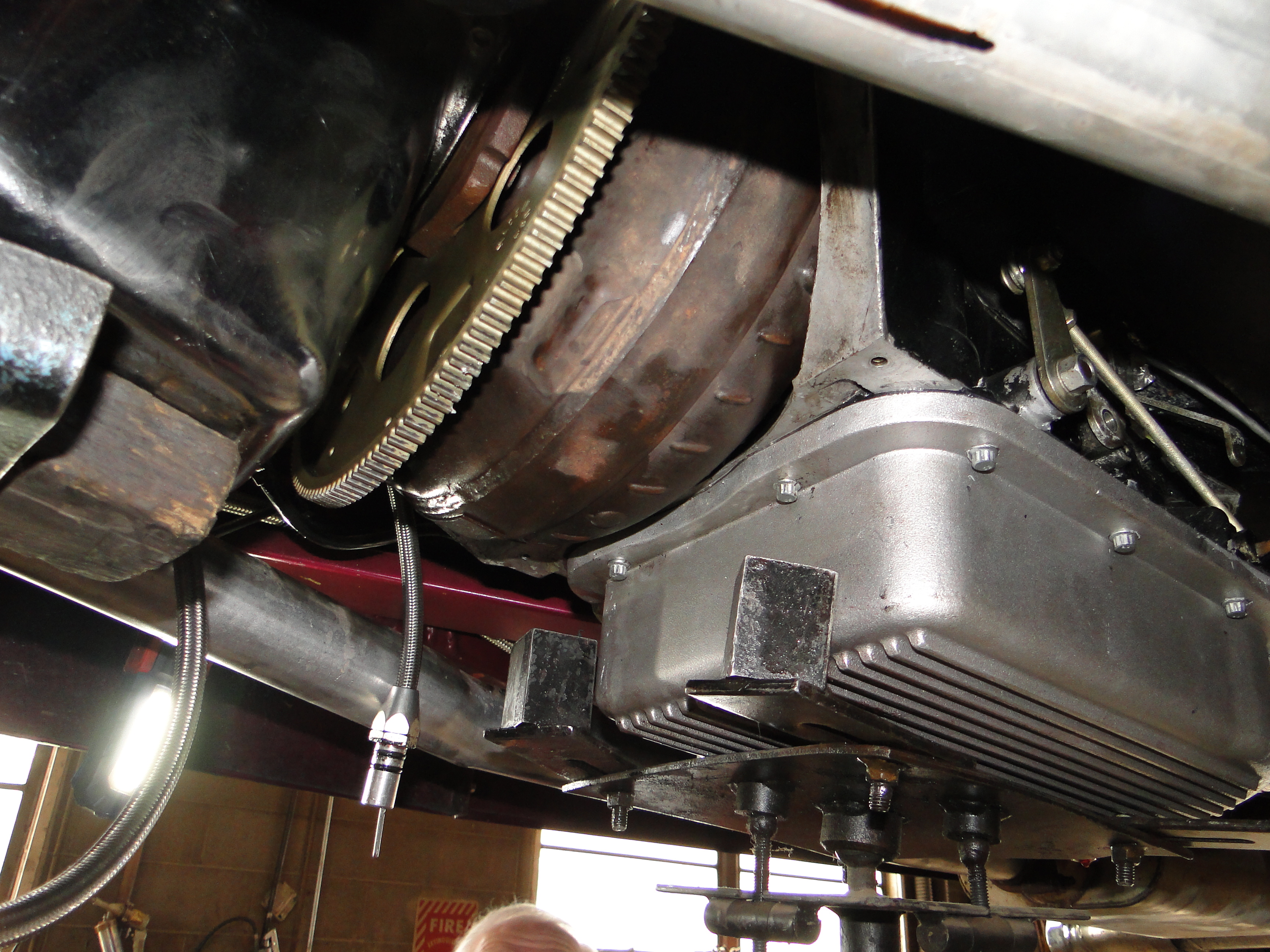
Transmission Seal Leak Repair and Gear Indicator
Installation
Last year Jim at Boffo Motors replaced the standard transmission pan with a larger
capacity unit. When the work was completed we discovered the
transmissions front seals were leaking. There just was not enough time to
do anything about it before the next snow fall. So Jim and I agreed
to address this next spring, which is now. Jim removed the
transmission replaced the front seals and with my help "Ha Ha" we reinstalled the
unit back into the car.
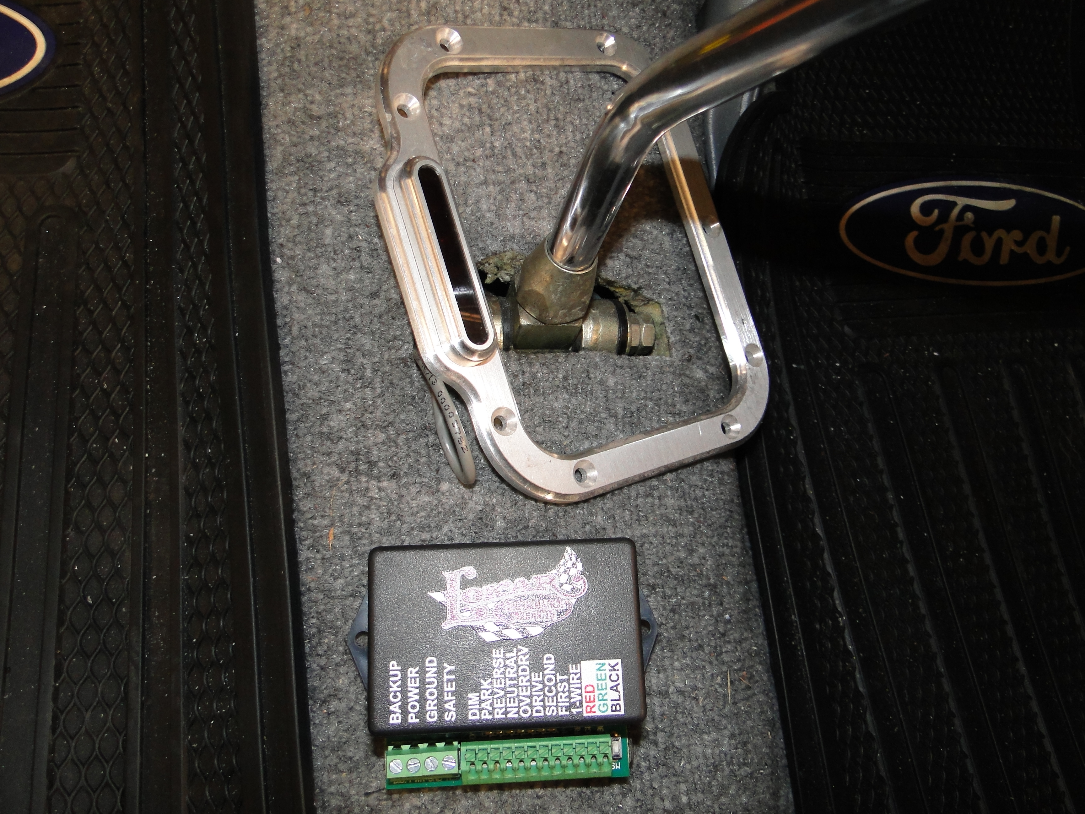
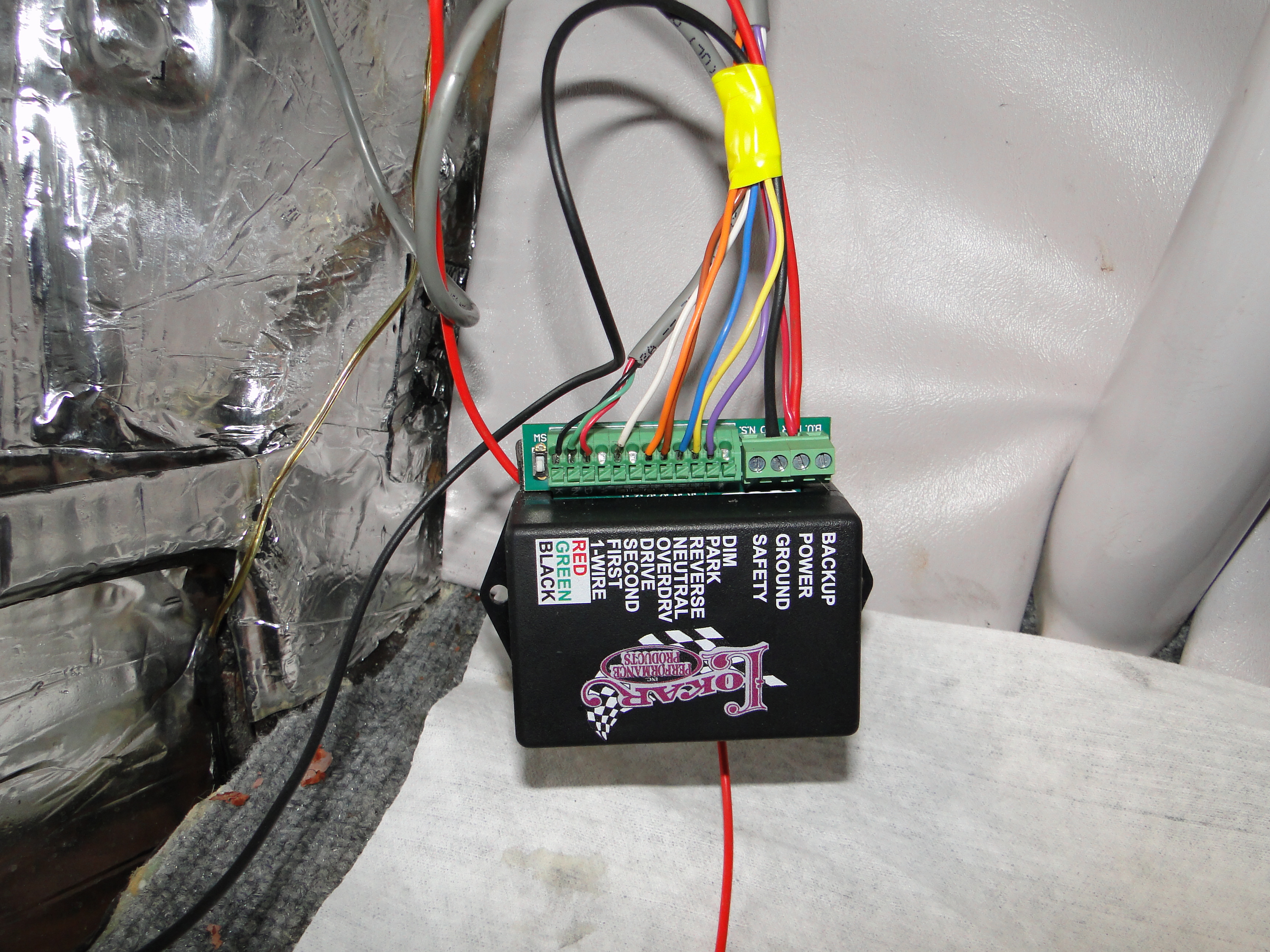
Another issue with this car from day one was it had no gear indicator, when you
went to put it in gear you had to count the clicks and guess what gear you were
in IE one click was Reverse, two clicks was Neutral, Three clicks was Drive and
so on. So I purchased a Locar LED boot shift
indicator that Jim also installed all the lower transmission parts too. Then
it was my job to perform
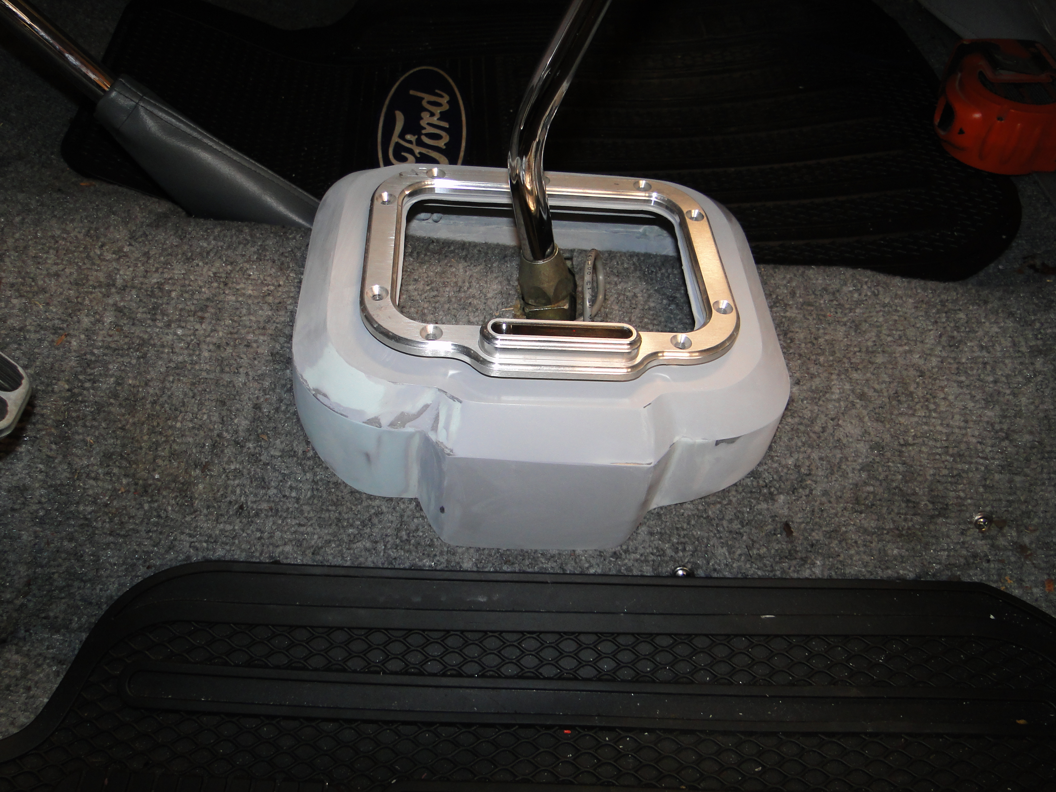
the wiring under the dash and fabricate a custom metal gear shifter boot mount.
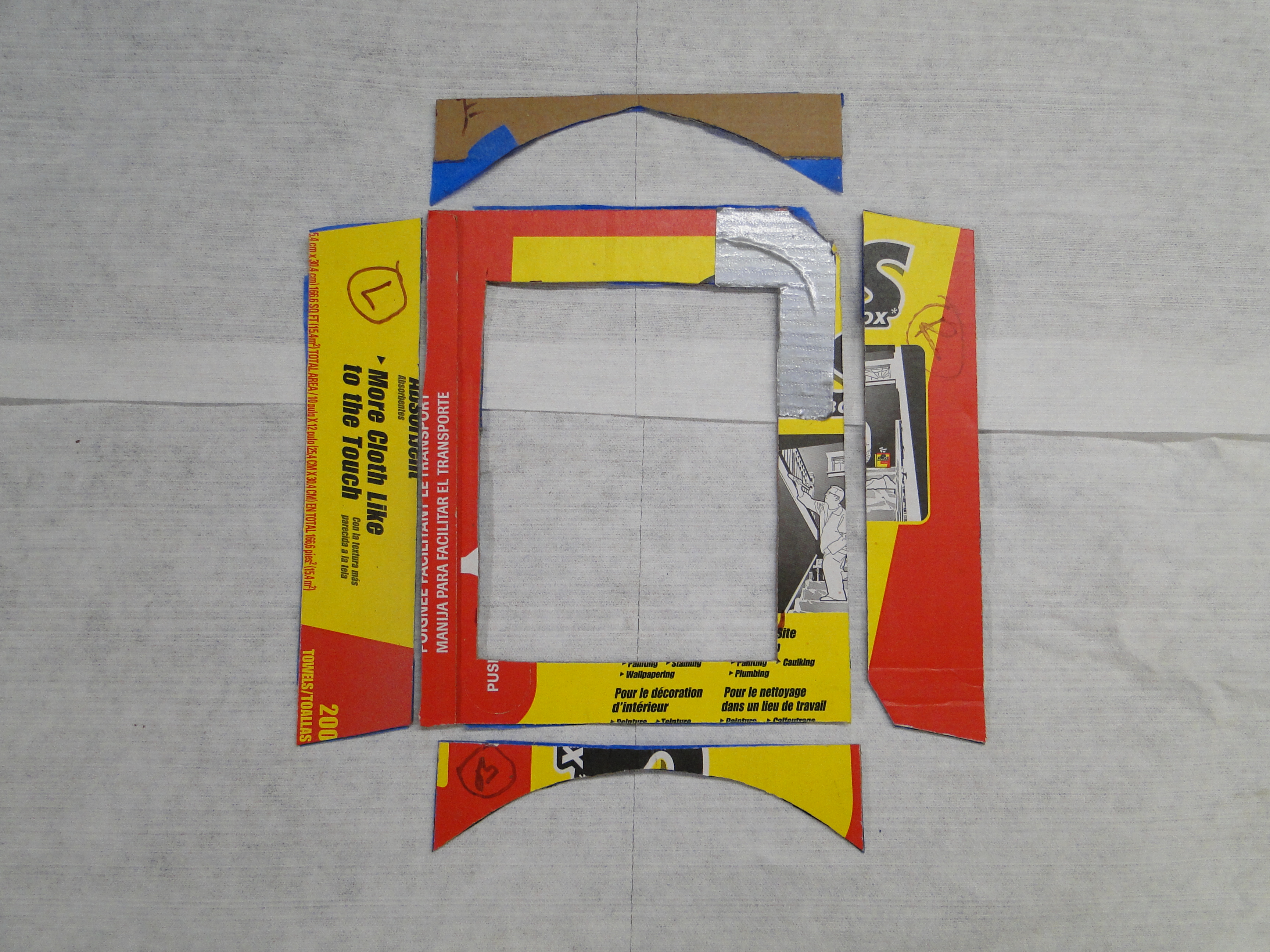
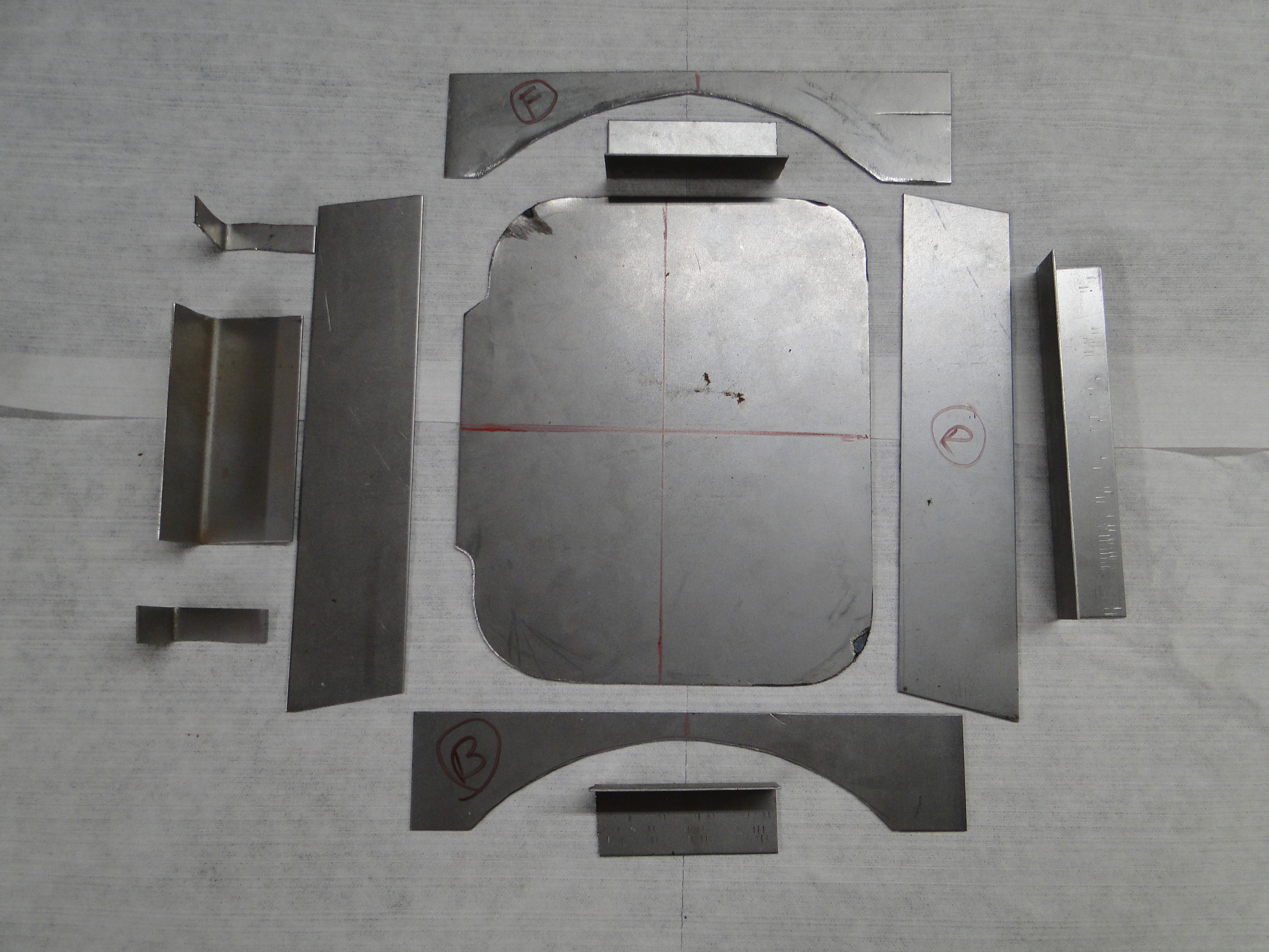
At first I was going to make a basic rectangle shifter base see cardboard
template. Then after the sheet work was already done I thought this
is boring! So I decided to add some curves and make it higher to
give it a little attitude. I had to hand bend the horizontal curves,
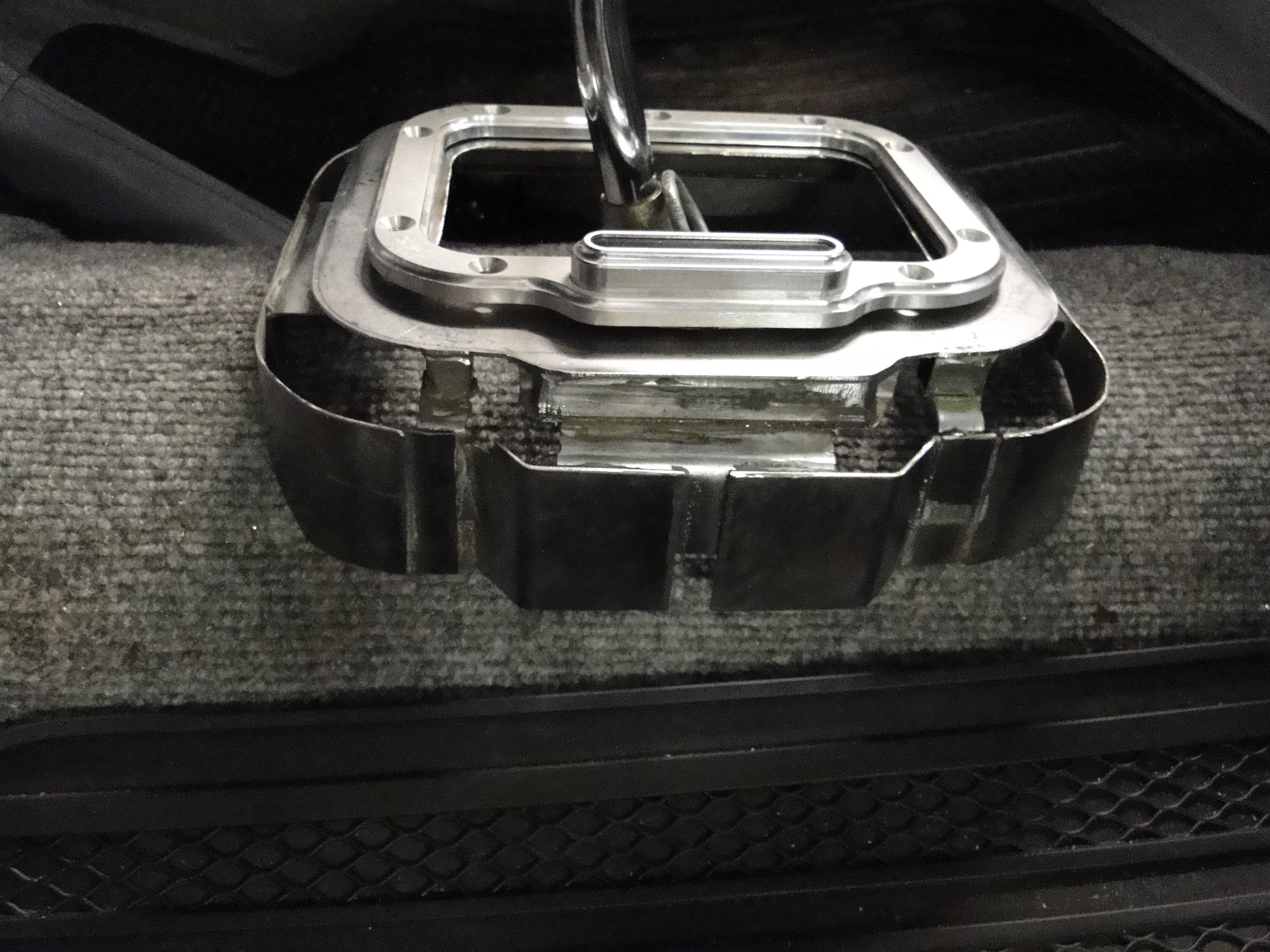
and use fiberglass to mold the top angles and filler to finish it off. When that was all done it was
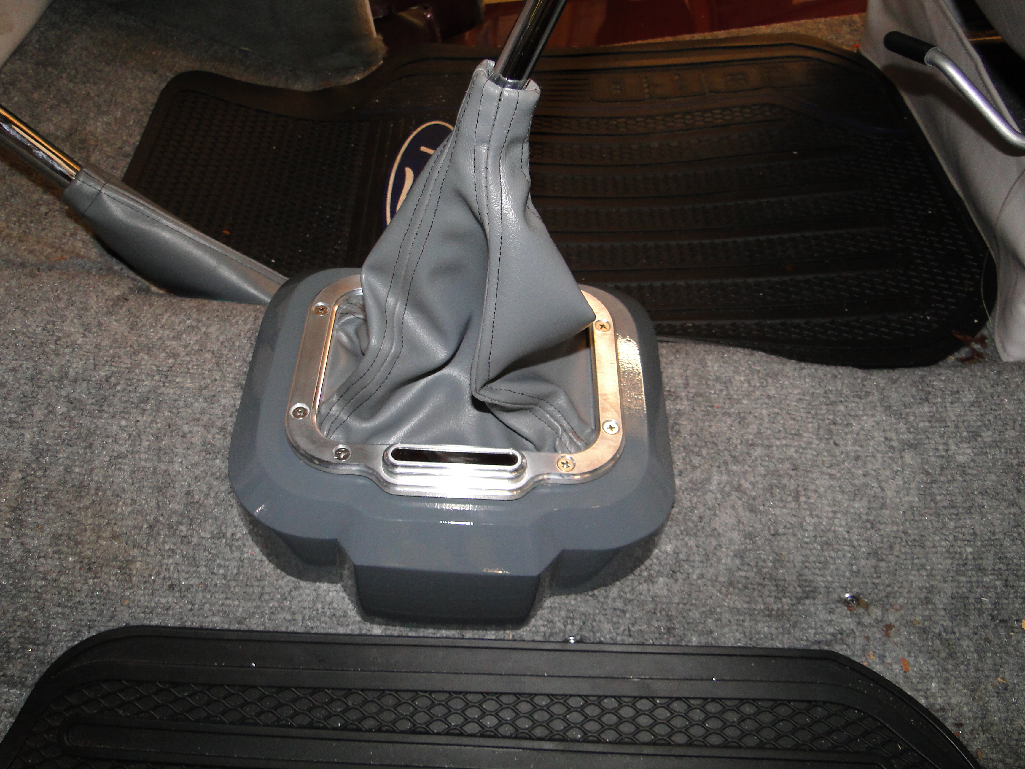
time for primer and paint. The next problem is the interior color
below the dash is grey. So I took a piece of material and had Mark at API, work
his magic on a color match for the boot mount paint. Mark has never let me
down, the paint color match is perfect.
Click any picture to enlarge.
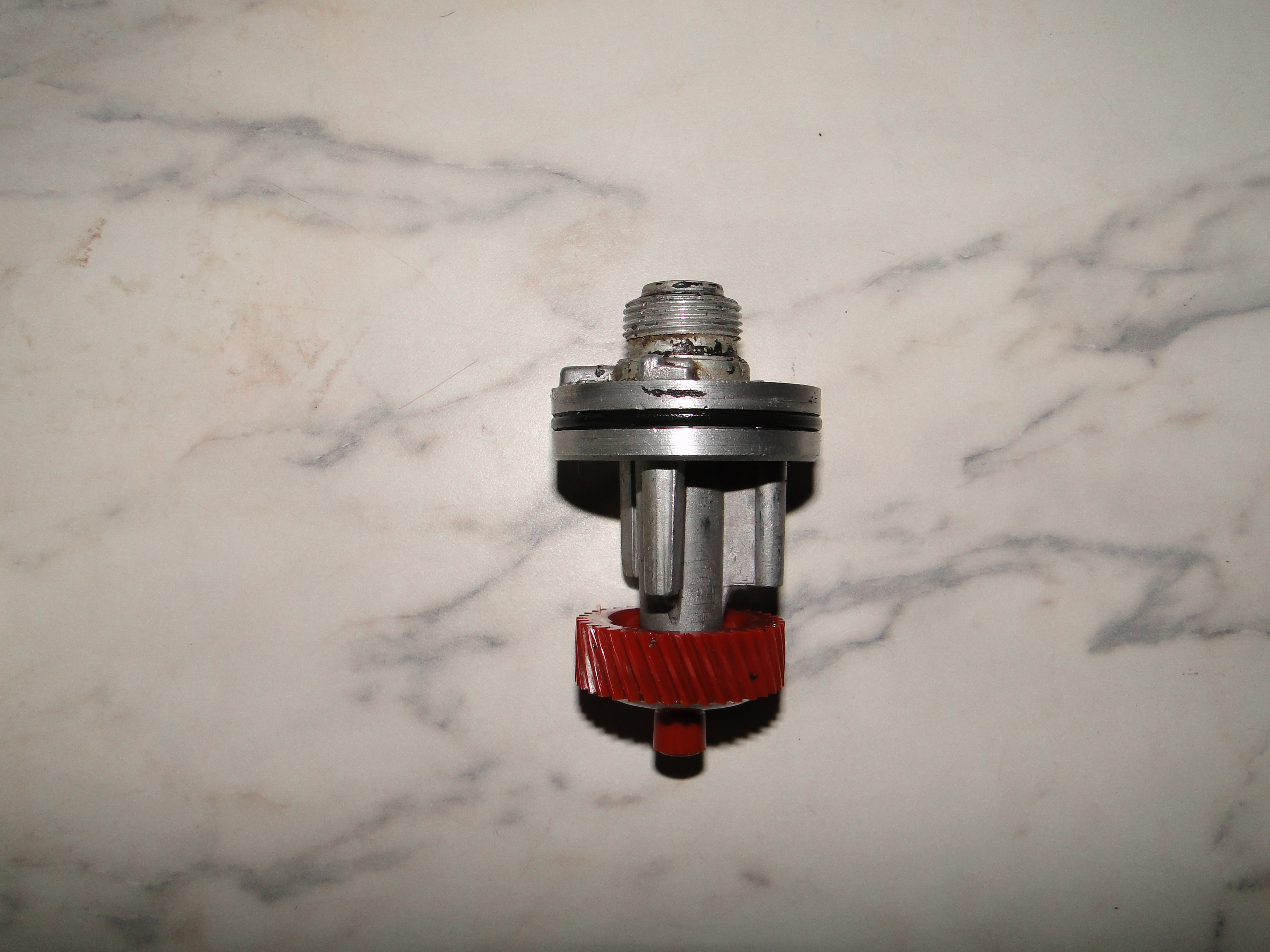
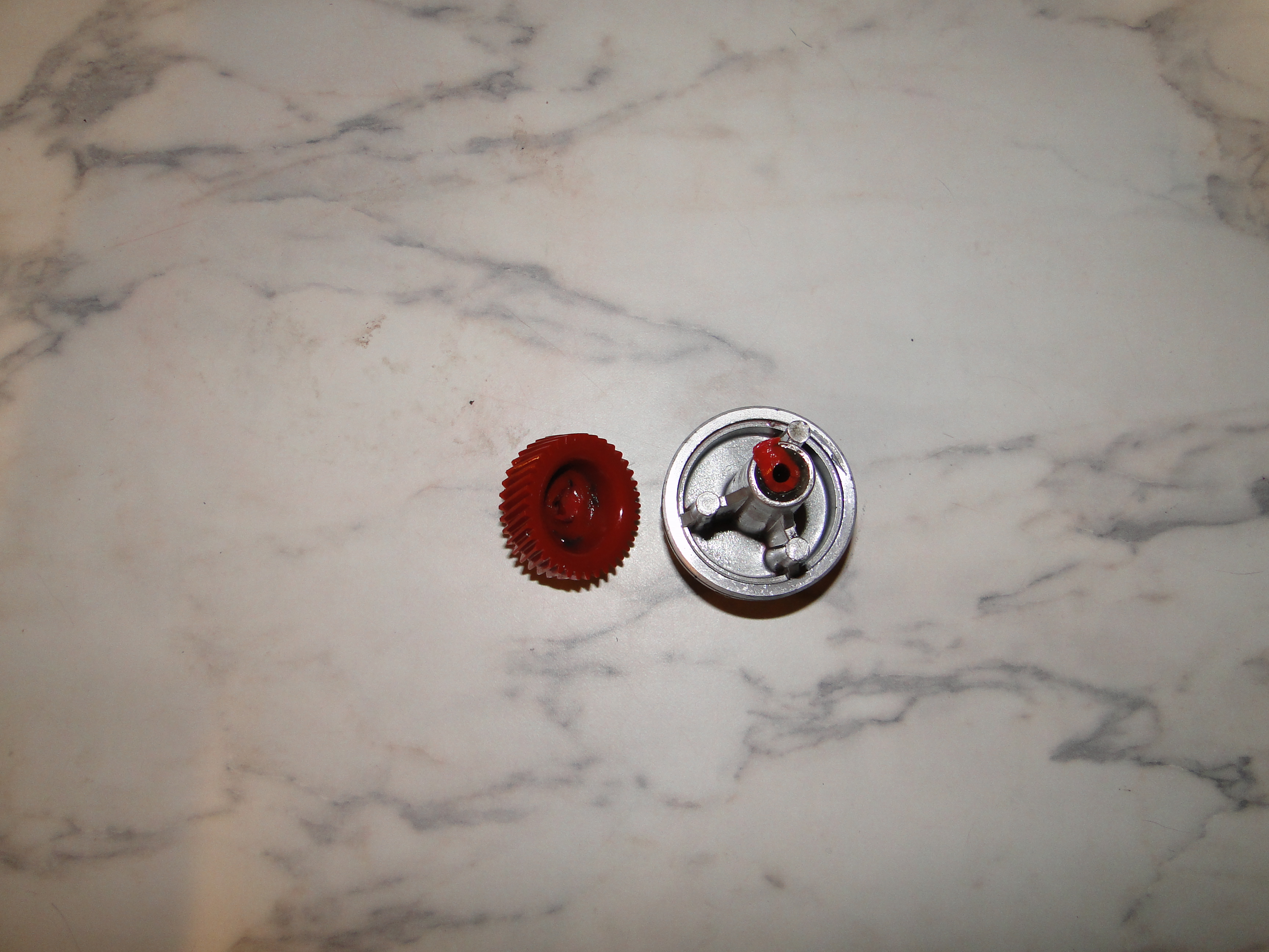
VDO Digital Speedometer Problems Part 2
When I drove the car to Boffo motors I noticed the
speedometer was not working again. While we were working on
re-connecting the transmission back up to the engine, I looked up and
saw the speedometer cable sending unit shaft sticking out of the
transmission, and for some reason I don't know why, I tried to spin it,
and I thought boy that spins real nice. Hold ON! not so fast
that's is not supposed to do that, it should be connected to a gear in
the transmission, and it should only
spin when the wheels turn. So I removed the sending units housing and
inspected the gears, I found no wear and both gears looked good, then I
determined that if I added a washer to the inside of the shaft, it would move the gear further in
to the transmission, and then
the gears
would then engage.
This could be another reason why the speedometer did not work, we will see.
Click picture to enlarge.
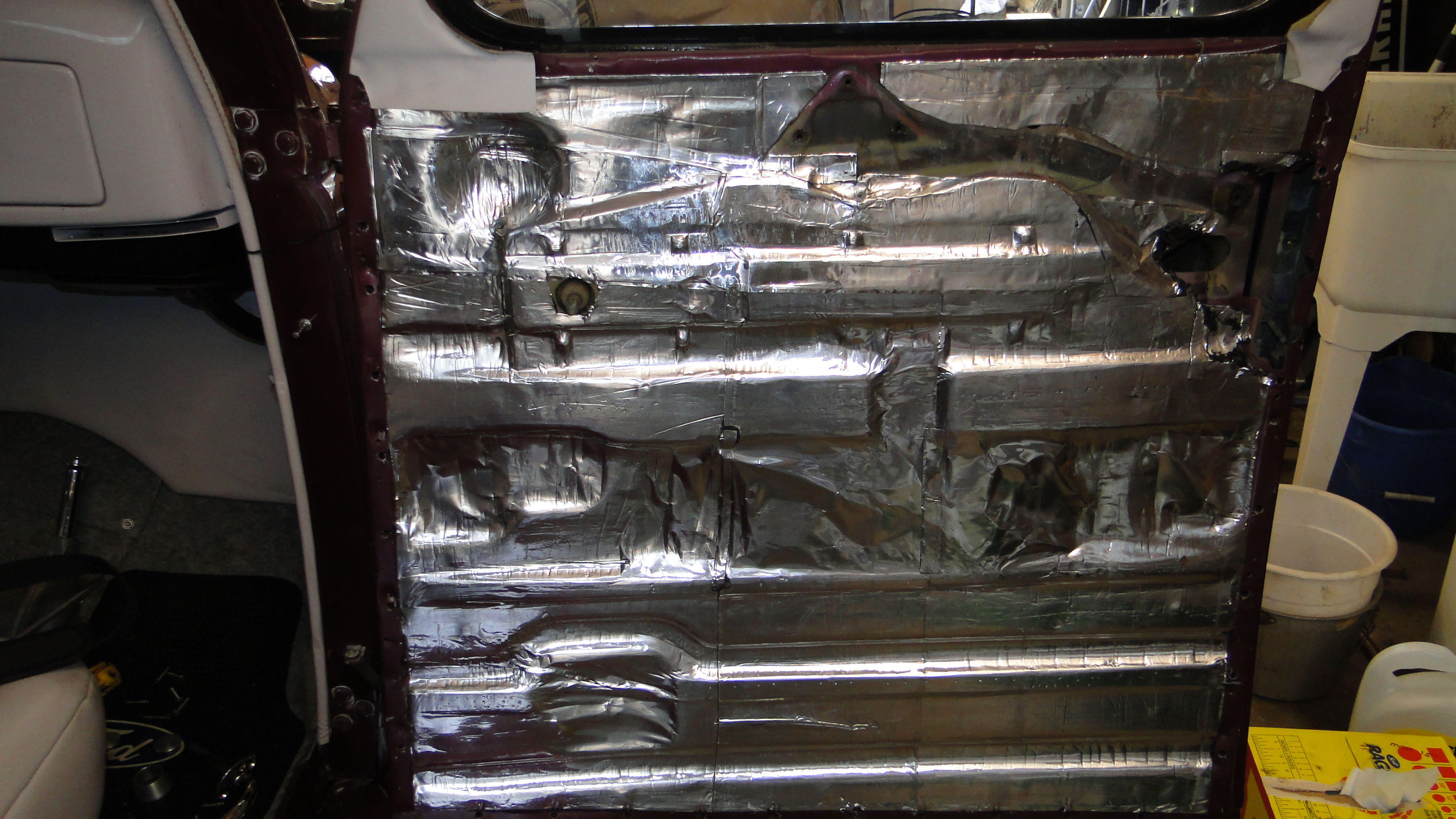
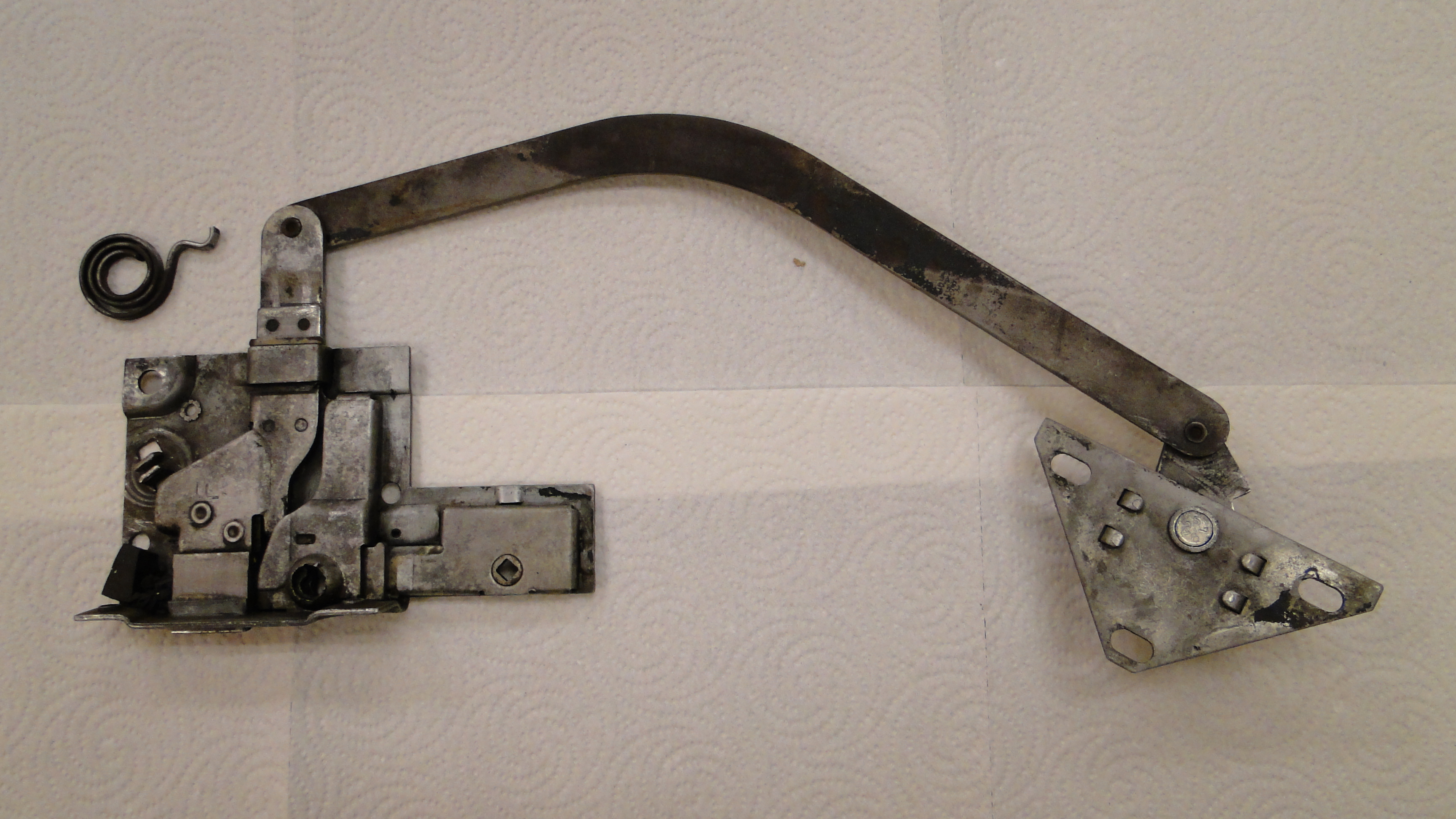
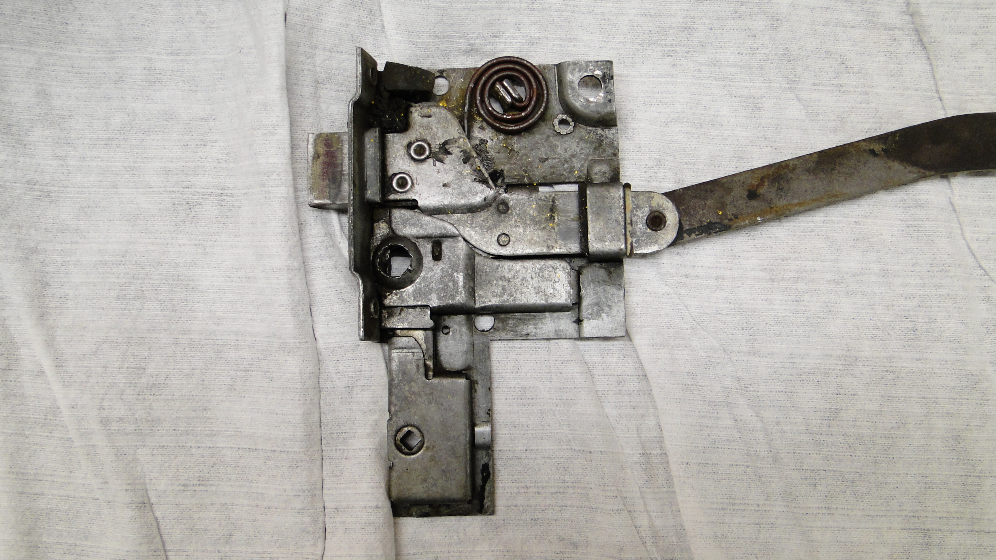
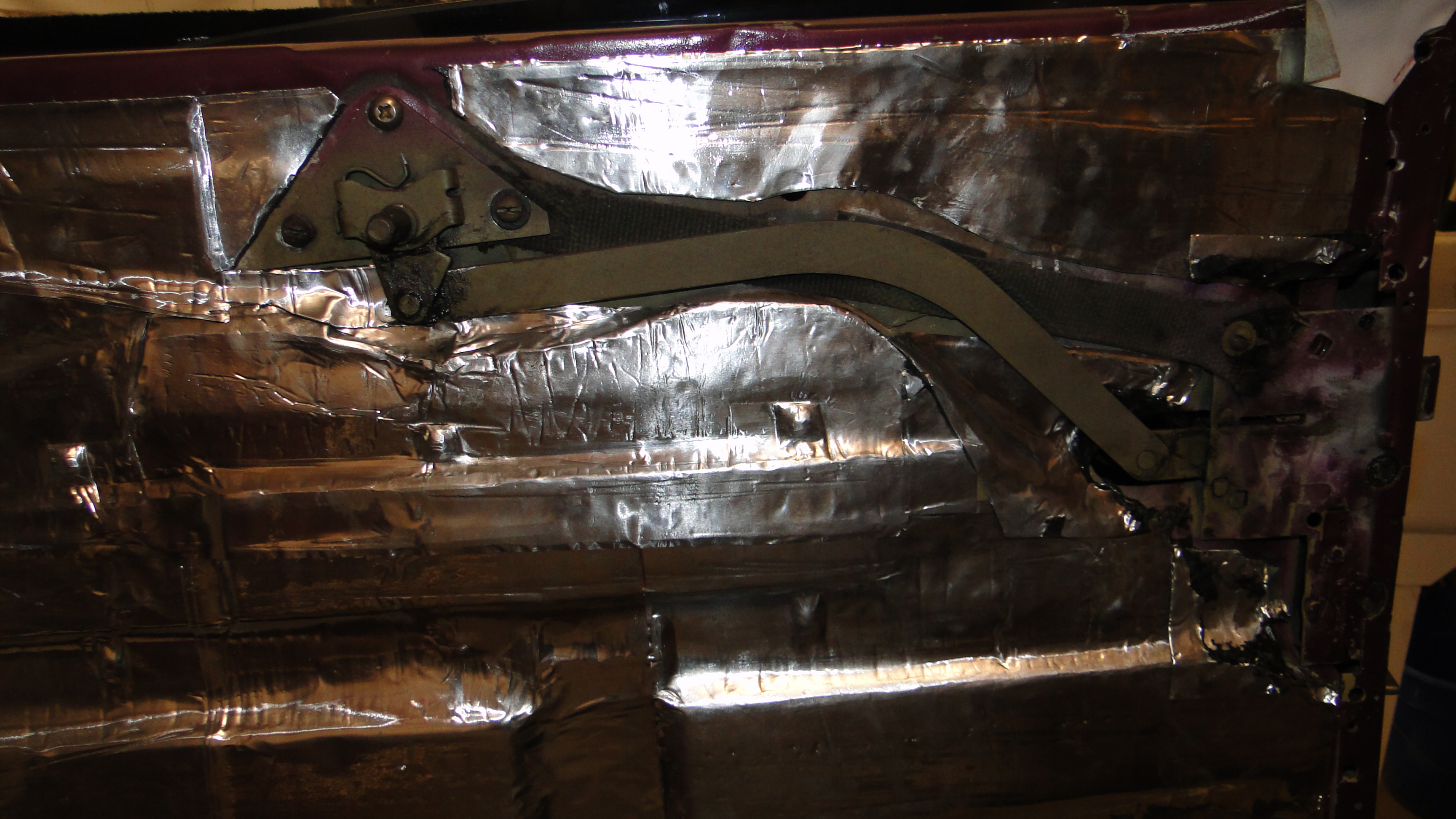
Passenger Door Repair
I tried to add extra grease to the passenger door latch for a easer
operation last summer, and it did not help at all. So its time to take
the door apart and see what the deal is, as it turns out the latch spring was
installed incorrectly. I removed the spring and went to re-install it
in the correct position and it snapped in two "of course it did". I did some R&D, and was told that the
1936 Ford early coupes had a small spring, and the later 1936 Ford coupes had
a larger spring. I had no idea which one to purchase so I purchased
both to be safe. Well the small spring is to small and the big spring is
to big. I had to shorten the big spring and re-shape the connecting
end to get it to work properly. After I reinstalled everything the
door open and closes easy, honestly maybe to easy.
Click any picture to enlarge.
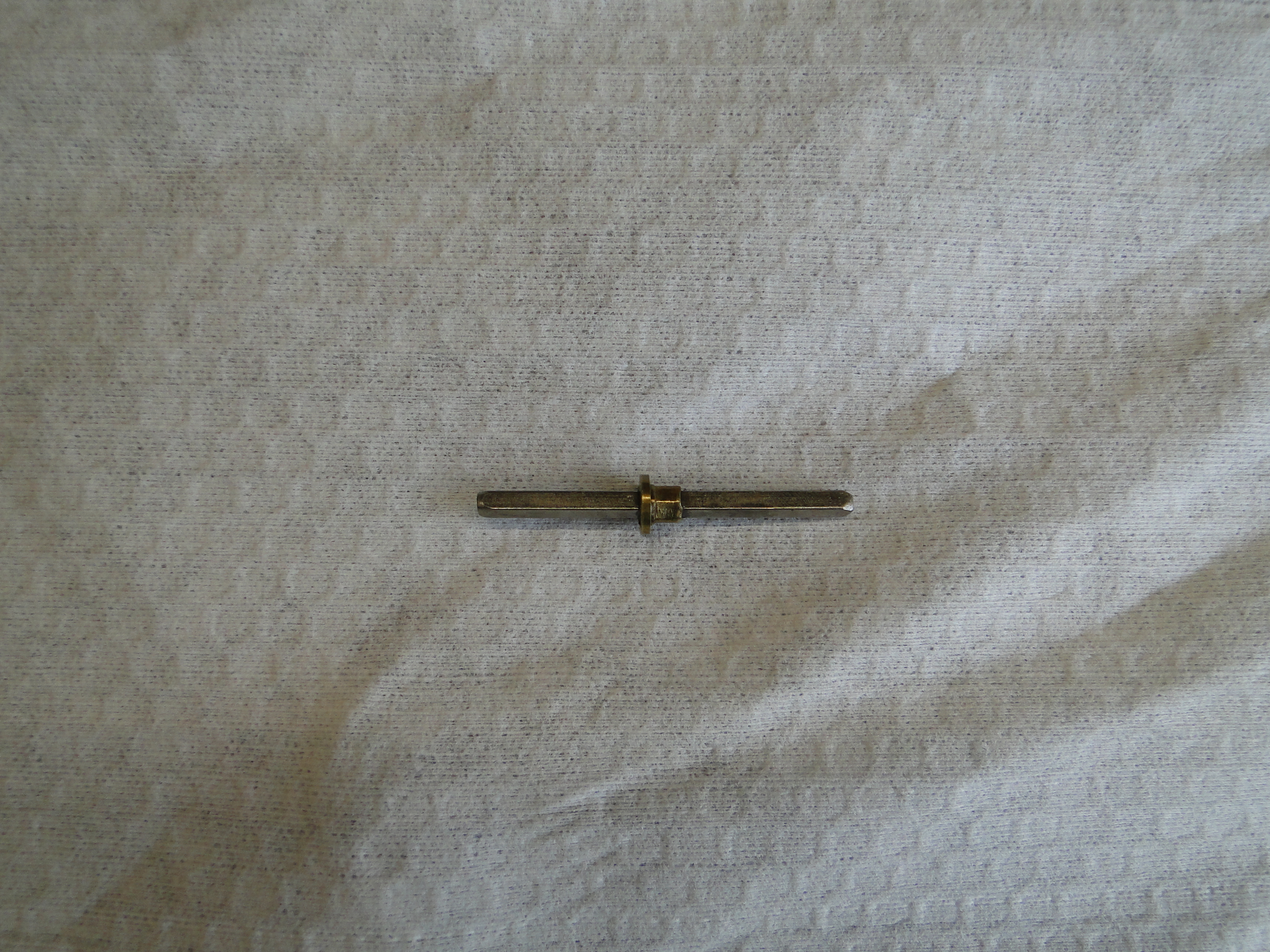
VDO Digital Speedometer Problems Part 3
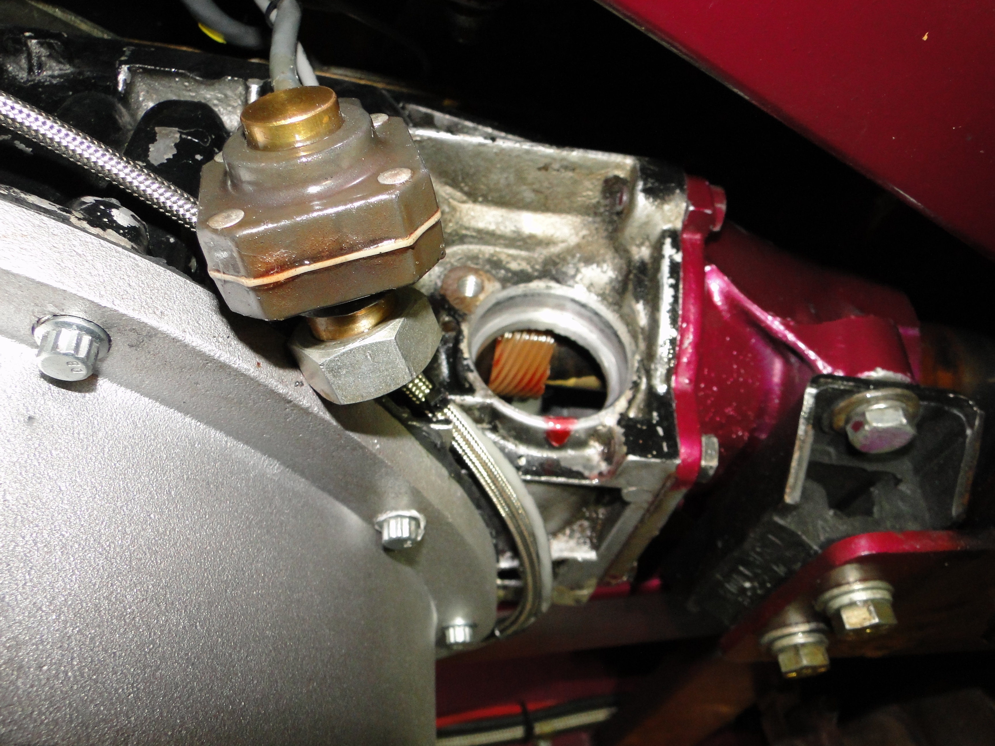
When I drove the car home from Boffo Motors the speedometer still did
not work. REALLY! Now I am pissed, and at
this point I am thinking I need to test everything from the Speedometer
to the sending unit housing on the outside of the transmission and all
its connections, so I started by disconnected the sending unit from the
transmission and spun the gear and the speedometer needle responded
"Well that works". Then I verified that the sending unit
shaft did not spin freely anymore "so that is working too".
I thought the problem has to be right in front of me, but where?
When I was examining the sending unit shaft I noticed it had a
bushing stop that was off center "That's weird". It hit me
like a ton of bricks, and I thought what if the shaft was installed
backwards from day one before I purchased the car, and maybe the long
end needs to go toward the outside of the transmission to spin the
sending unit. Once I did that, it was like magic and it did
not work WTF! I need to walk away and work on something
else for a while, then come back to this
with fresh eyes later.
Click picture to enlarge.
June
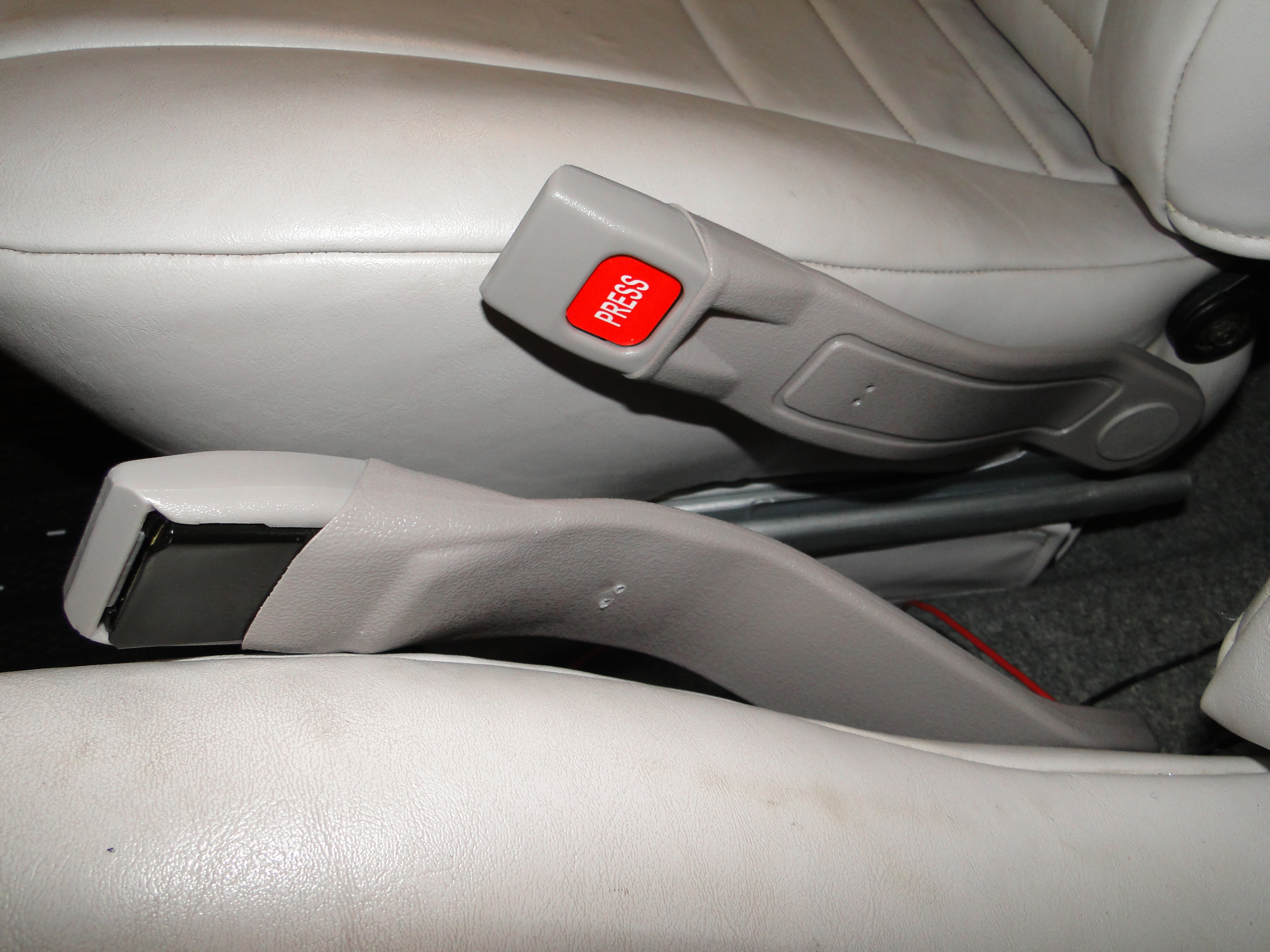
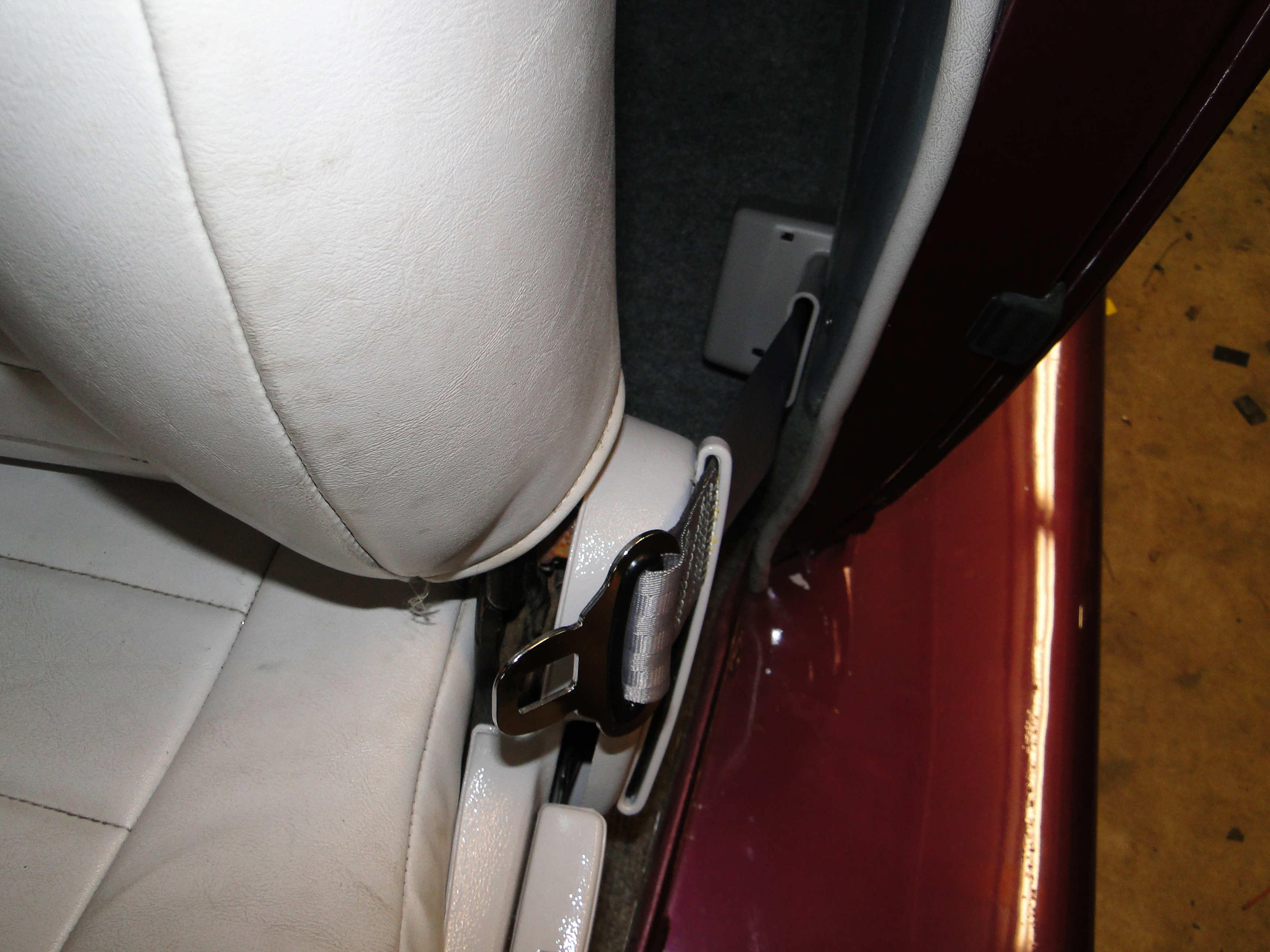
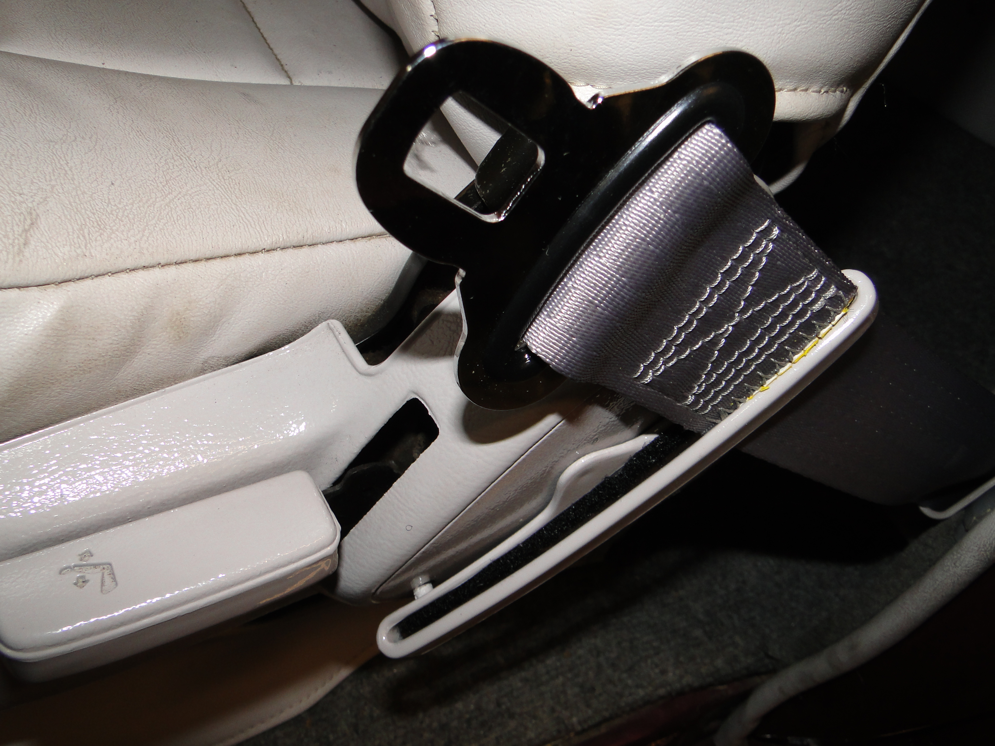
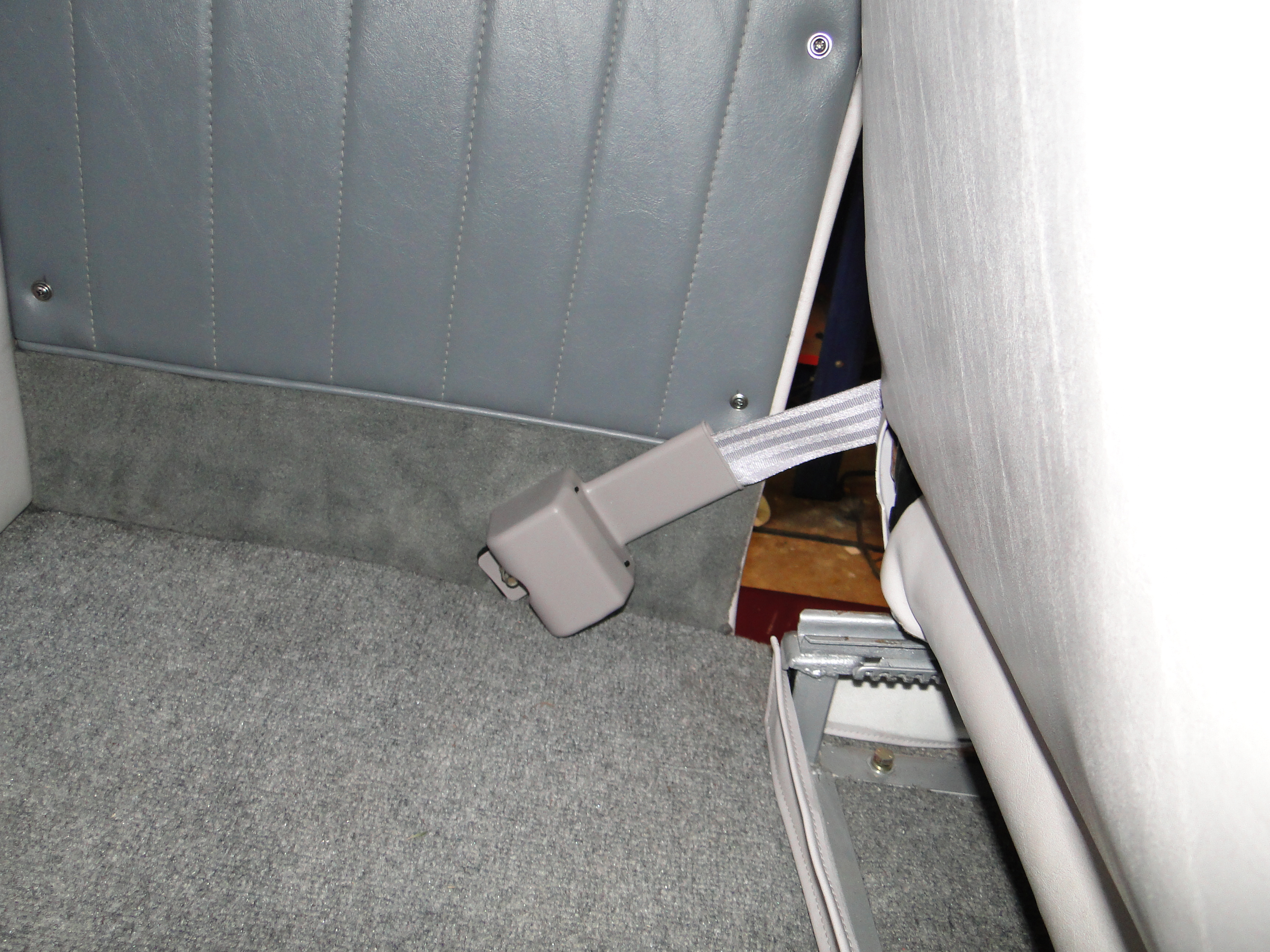
Seat Belt Installation
I have never had seat belts in this car, and now that
my kids want to drive her. She needs to be safe. Installing a
three point seat belt system would prove to be to difficult, costly and time consuming,
so I went with a retractable two point belt system that Boffo Motors had custom
made to match my interior. I drilled holes for the one end to mount
to the side frame of the car, and the other side just mounted to the seat.
I also used part of a Velcro strip that I cut in half to serve as a pad in the
belt guide to reduce noise. Nice and simple for a change.
Click any picture to enlarge.
Finish Interior Installation
Now I want to finish the interior, from the windshield
over the doors, and down the side windows. I need to make a
cardboard templates, and then the actual panels. Then we need to cover
the panels, and then finally mounting them.
Click any picture to enlarge.
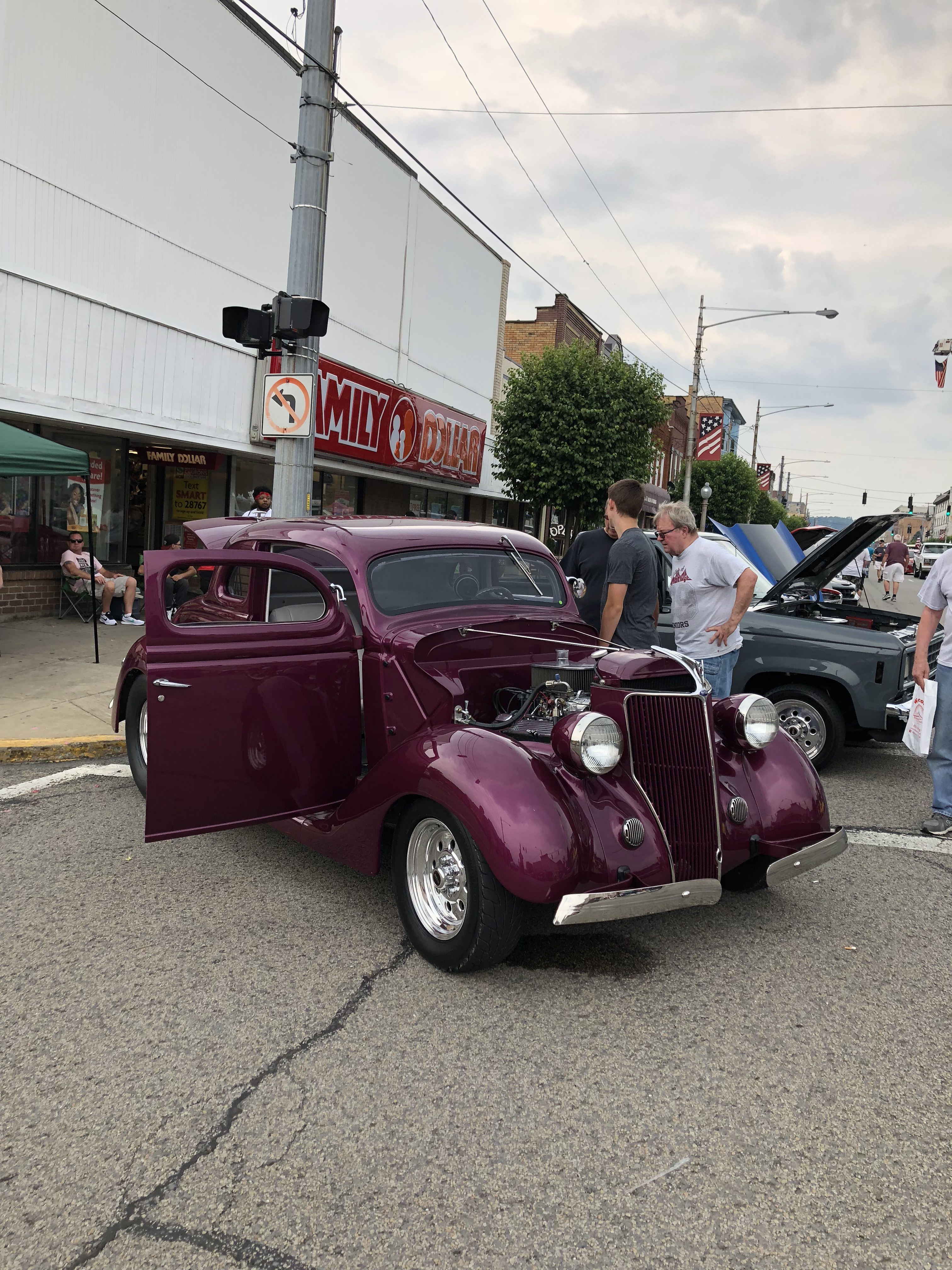
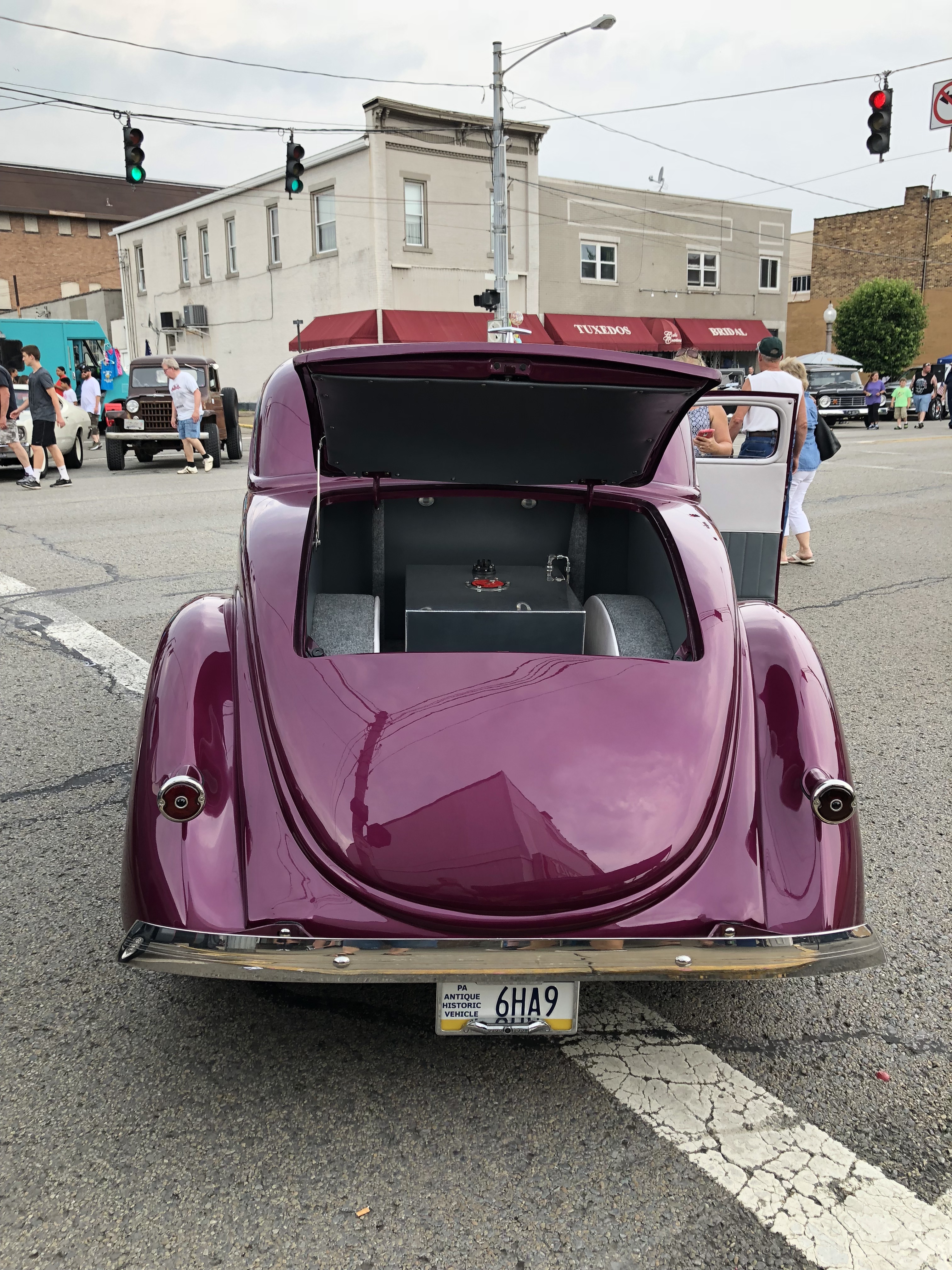
The Curse Of The Beaver Falls Car Cruse Is Over!
For the first time in over five years this car finally
made it to the Beaver Falls car cruse with out breaking down or acting up. The
weather tried to rain me out, that was not going to happen.
Click any picture to enlarge.
July
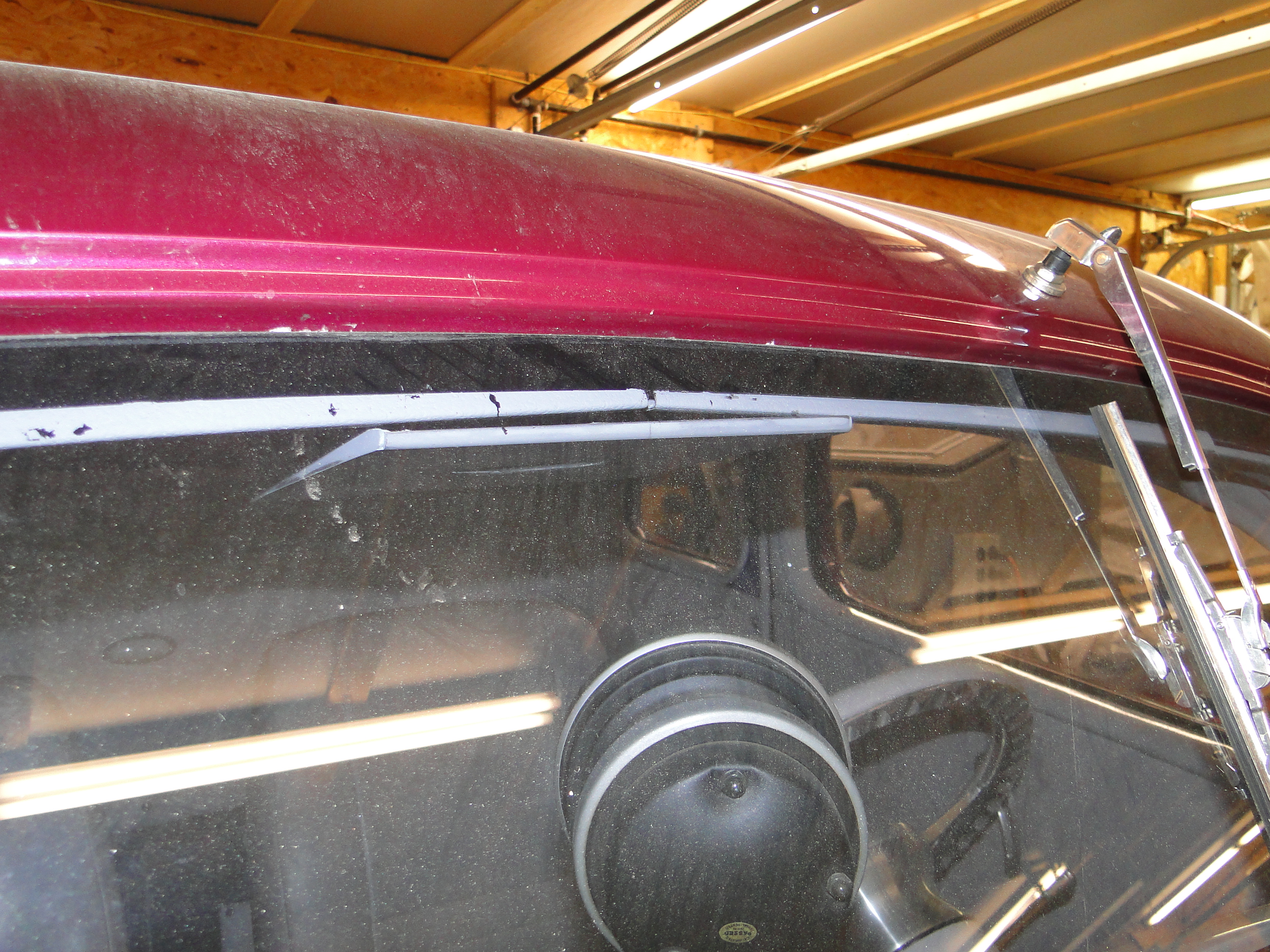
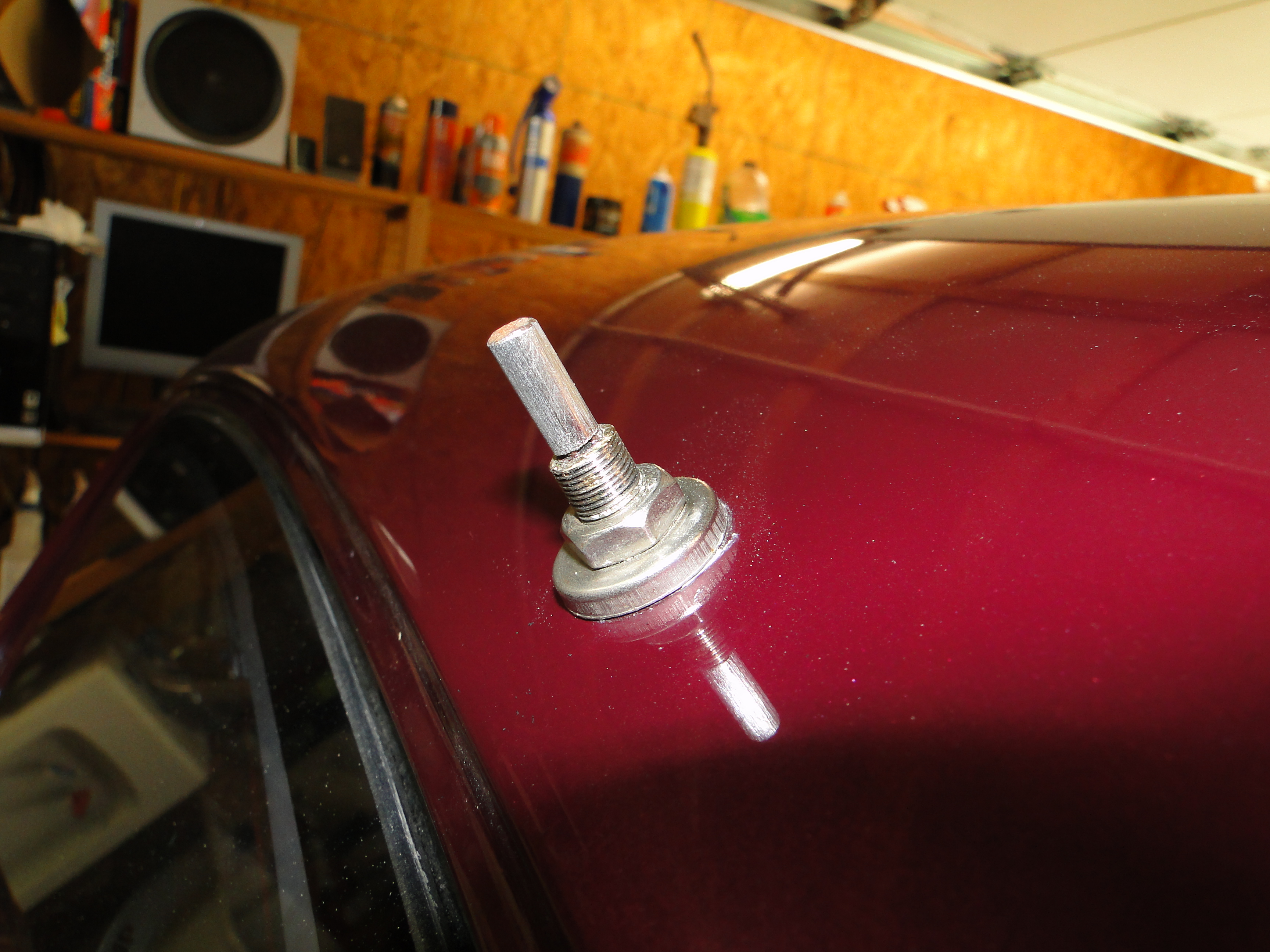
Windshield Wiper Modifications
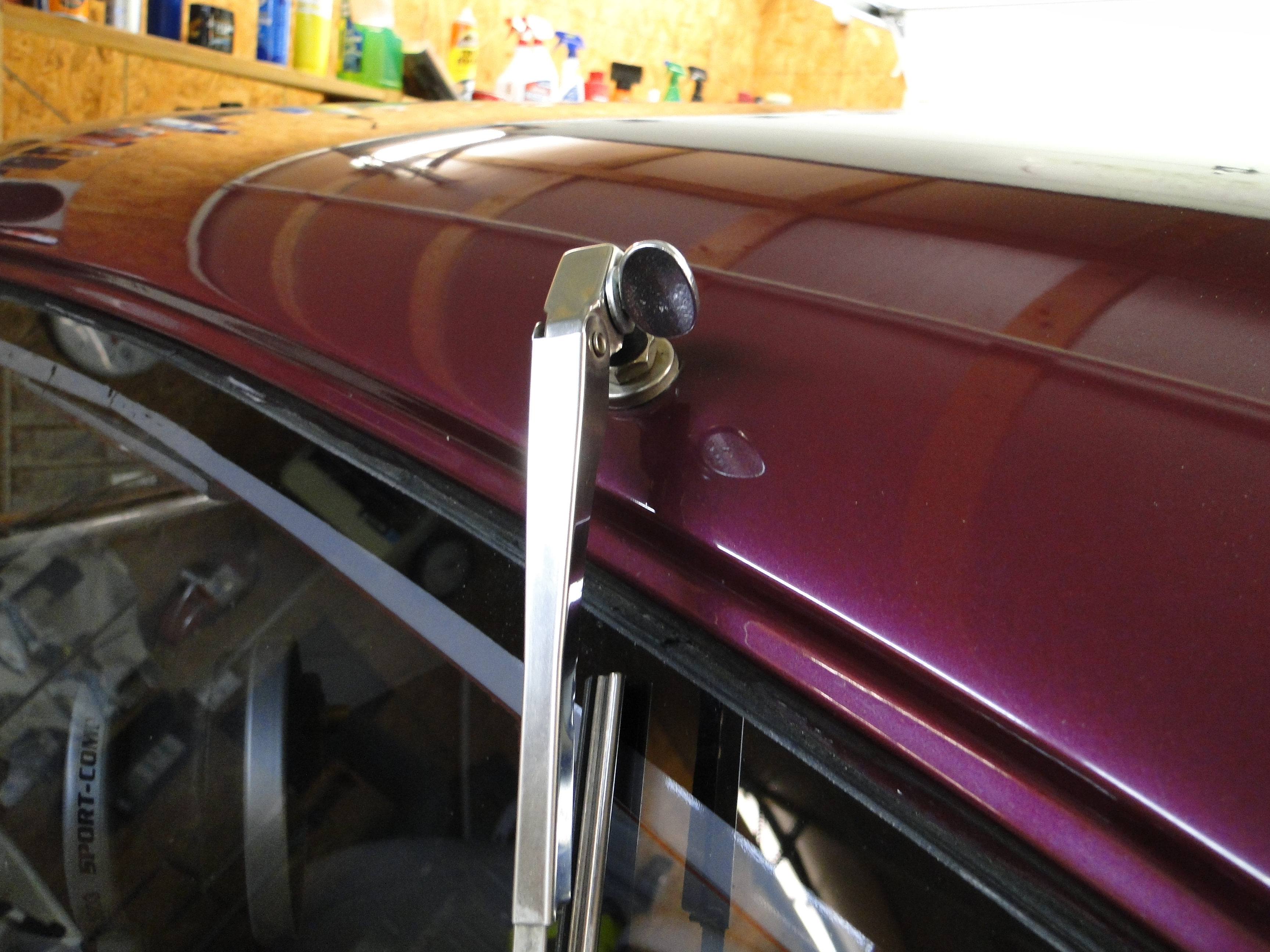
Well I don't know if its OCD or just in my mind, but the front windshield is so
small that the wiper arm and blade seems to take up way to much space, and when
I look down the road to drive I see two wiper blades. Then it
becomes twice the problem. So I though what if I make the wiper arm and
blade removable like on my Austin Healey. I replaced the locking
bolt with a winged bolt that can be tighten by hand. Job done right?
Wait not so fast, when I needed my wiper to work in the rain last week, I turned
it on, the motor ran but the wiper blade did not move. So I though this is an easy fix and went to
tighten the bolt by hand guess what I could
not tighten it any more. Well I have to come up with a new plan.
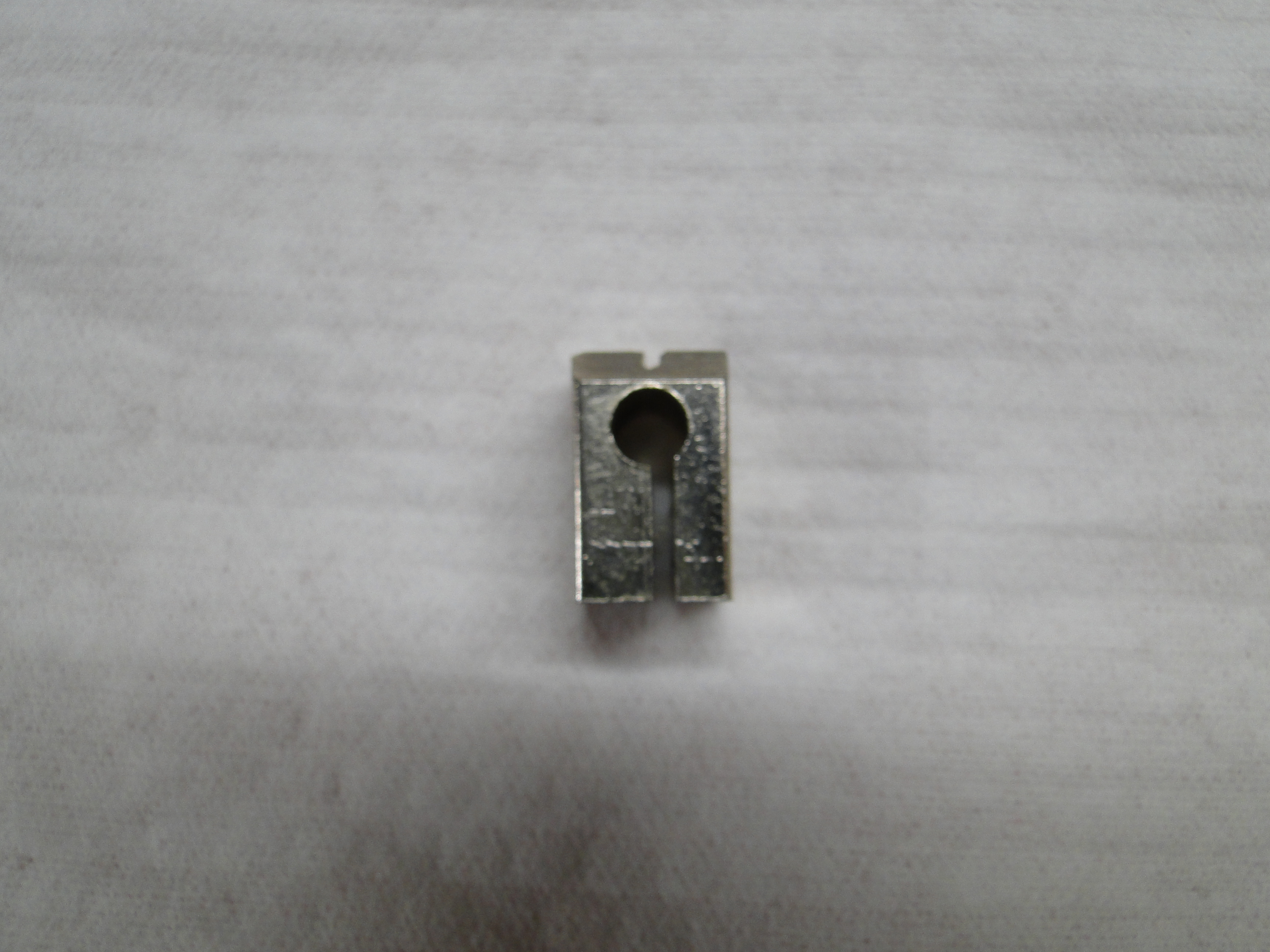
I disassembled the wiper blade head and noticed I could not get the cast steel
mount point to close tight on the motor shaft when I tried to tighten the wing nut.
I decided to weaken the mount point by cutting a notch on the opposite side of
the shaft hole to allow it to grip the wiper motor shaft better, and it seem to work
just fine now.
Click any picture to enlarge.
VDO Digital Speedometer Problems Part 4
Well I am back on the speedometer problem again, so I called a VDO service
center and sent them photos of the transceiver unit to make sure its
compatible with my VDO Series one speedometer. Hoping that is the
problem and to my surprise they said my transceiver was a original vintage
series one unit and it should be fine. At this point I removed the
speedometer housing from the transmission, and I got a real eye opener the
housing shaft guide was worn so bad that the gear would wobble while spinning.
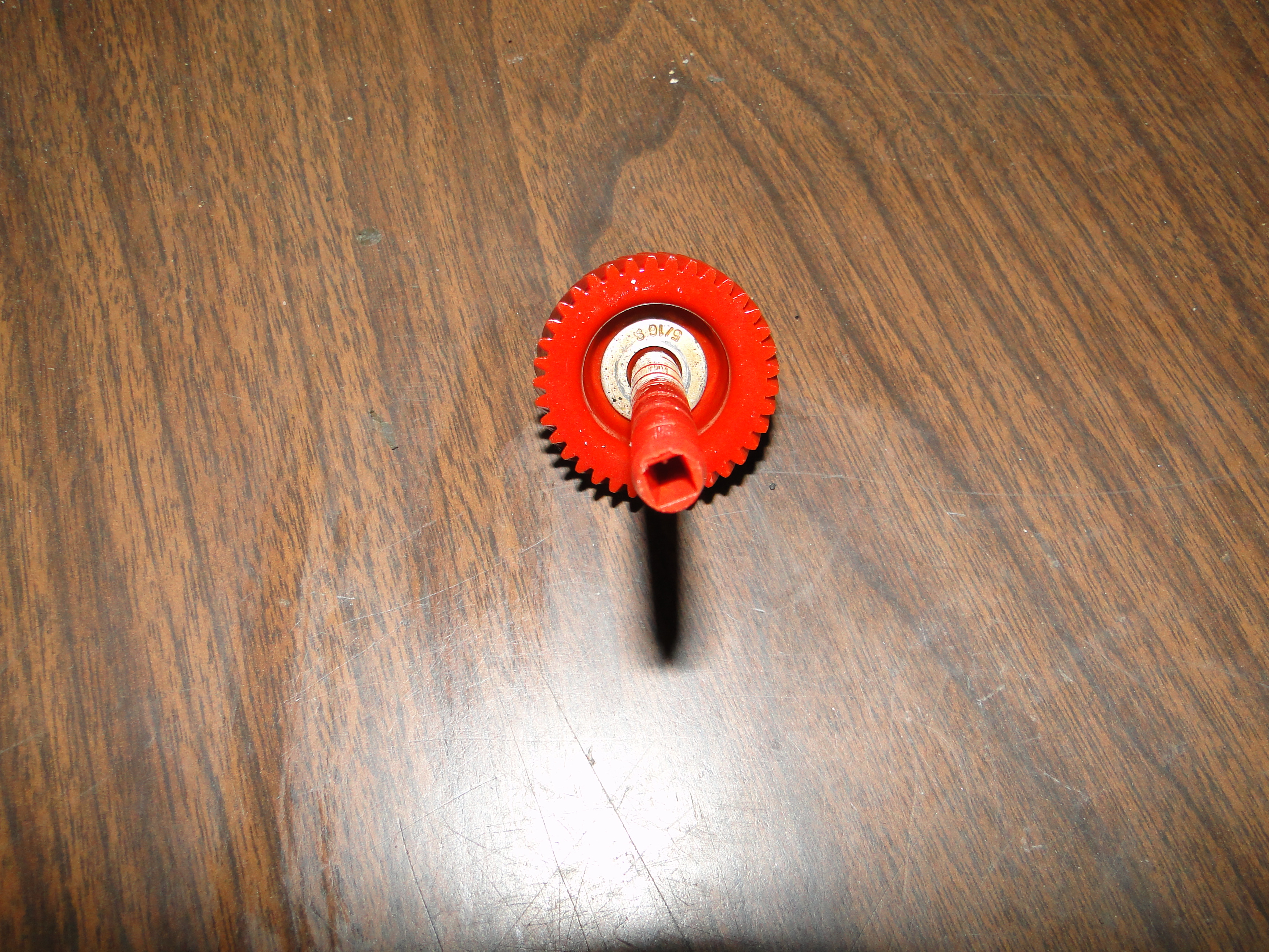
I replaced the housing and when I went to install the old gear, and somehow I broke
the gear shaft. So here we go again, I purchased a new gear and installed
it and now we have a speedometer that actually works right, wait not so fast.
Now we have a calibration problem which is better than what we had before,
according to my speedometer I was doing 50 MPH in my driveway, and, I was also
doing 110 MPH on the street in front of my house. Once
I get the
calibration problem
corrected I should be good to go.
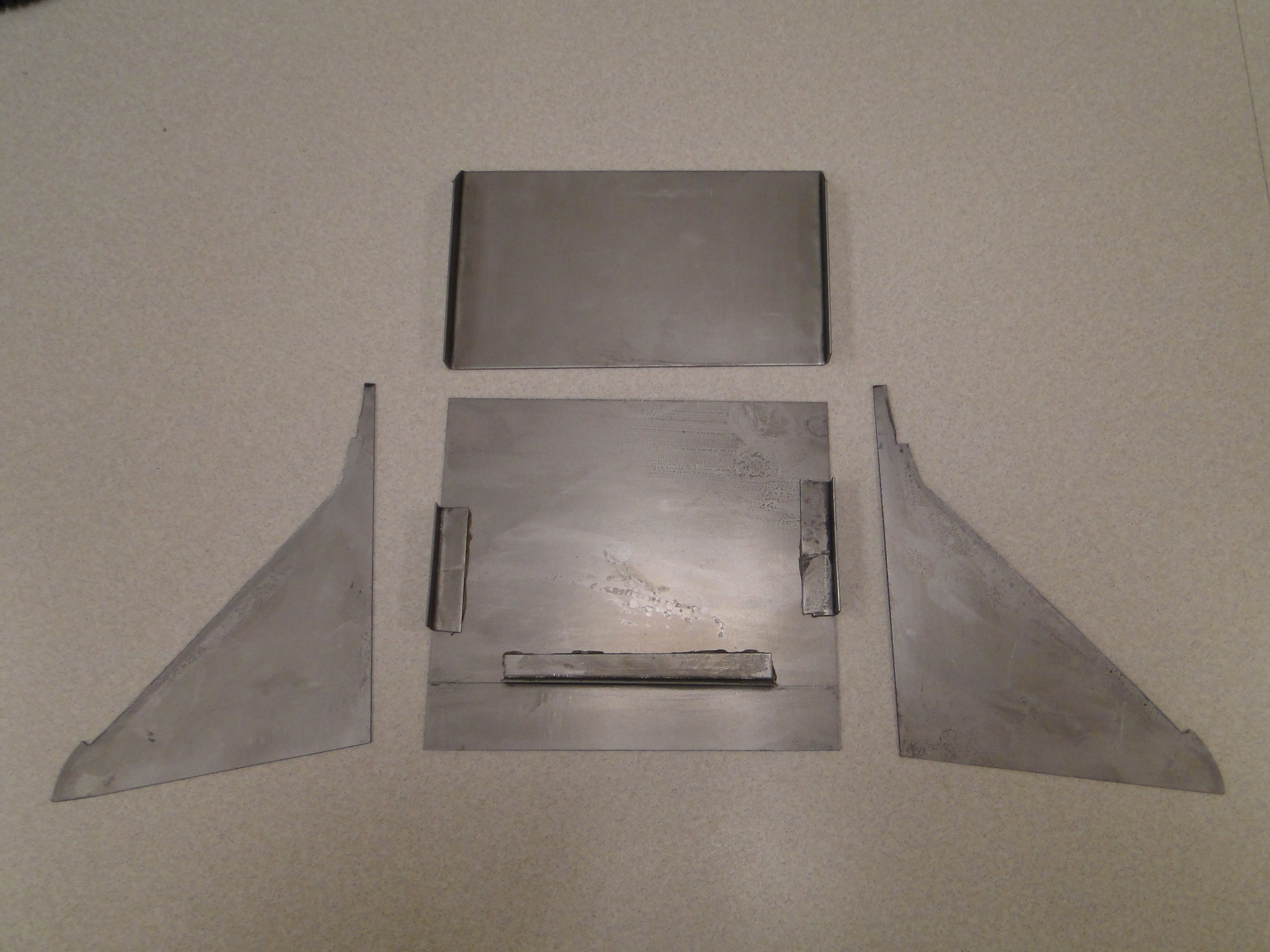
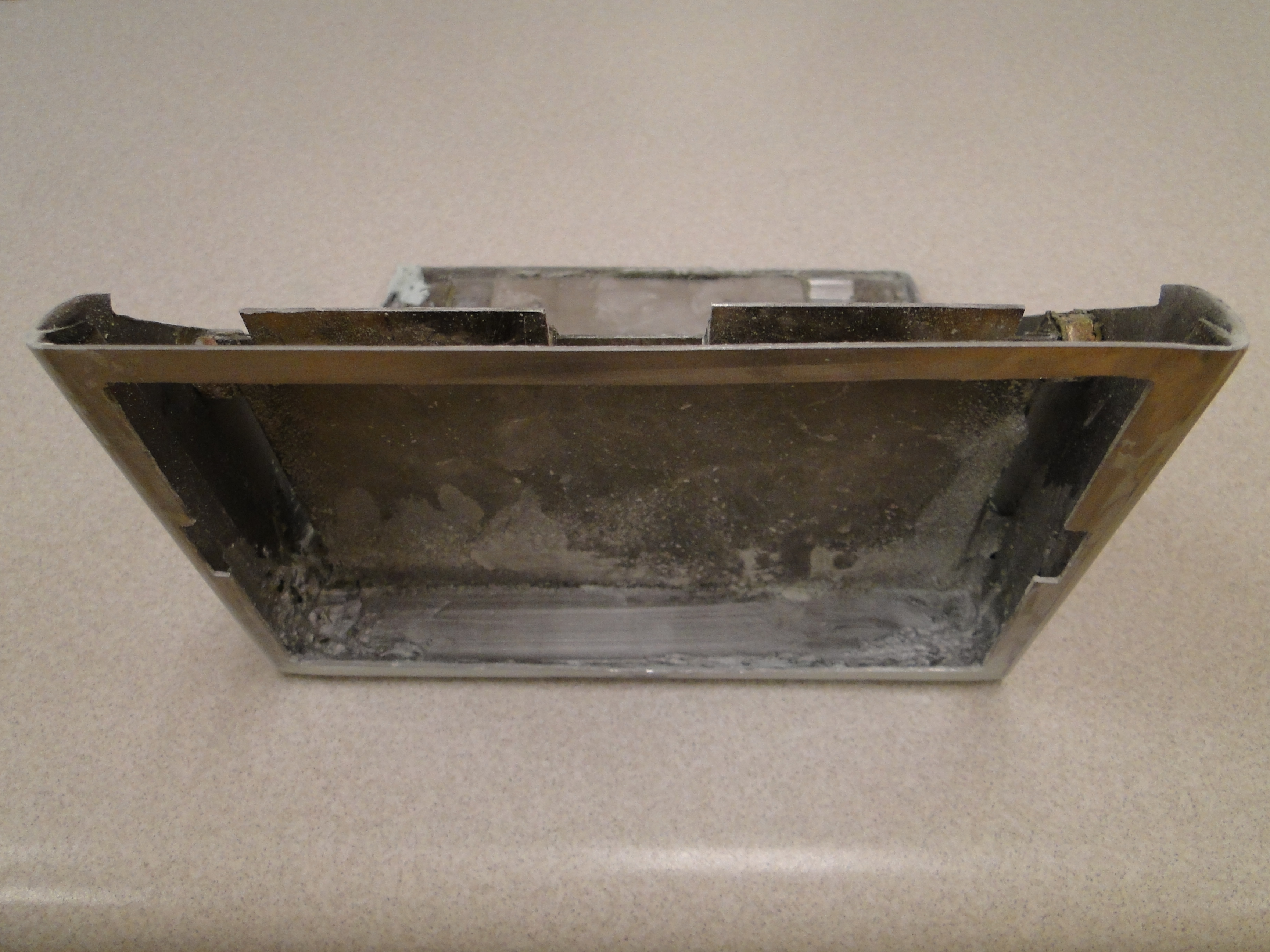
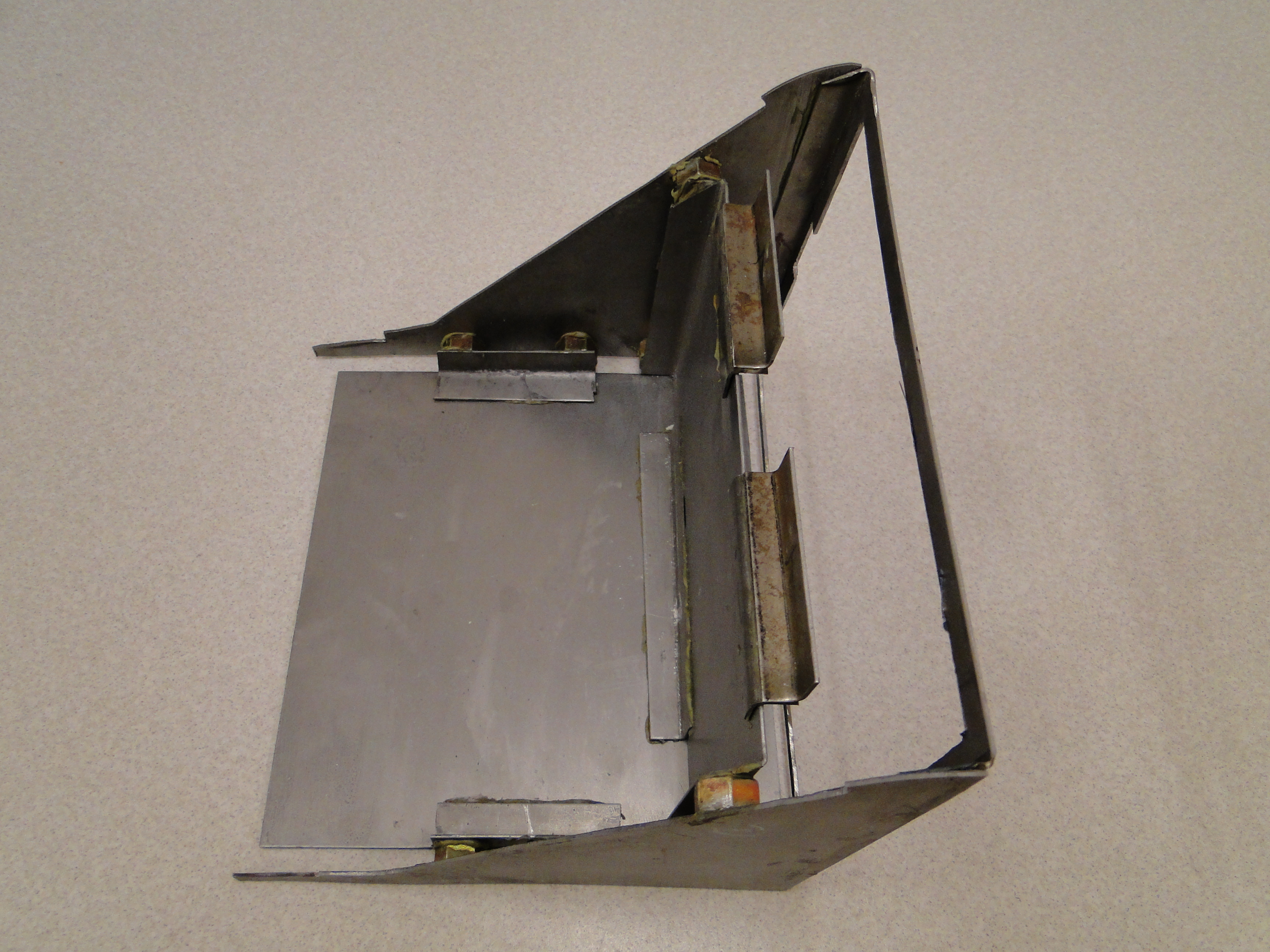
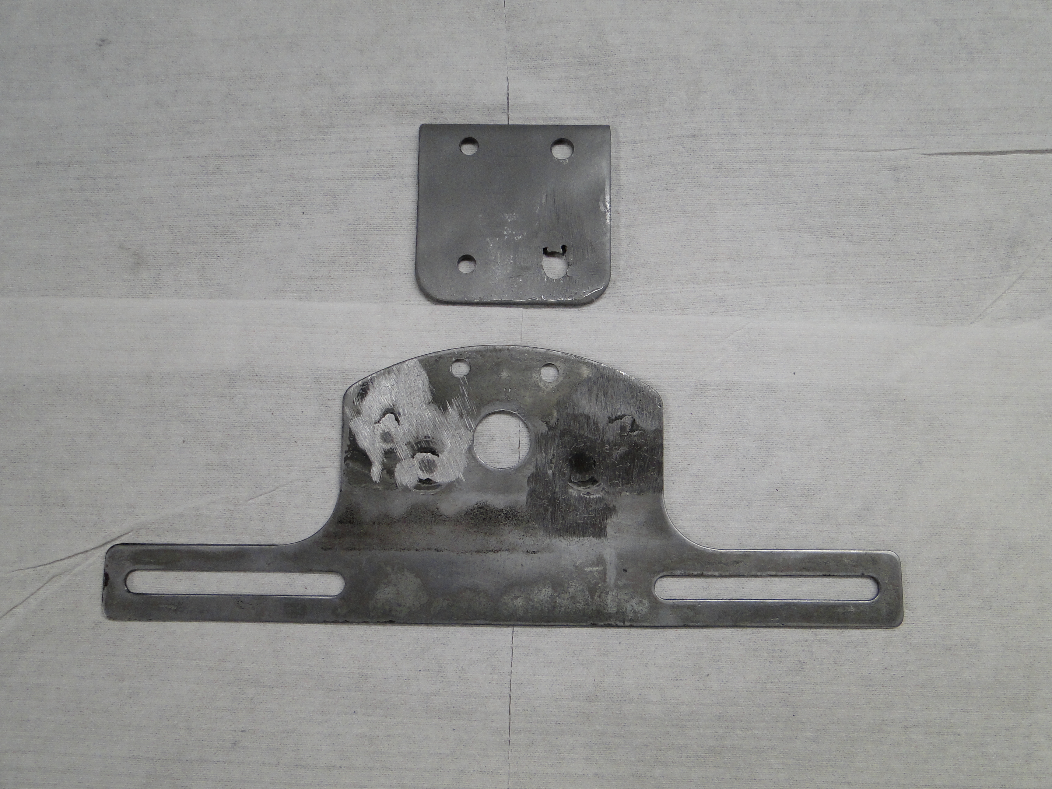
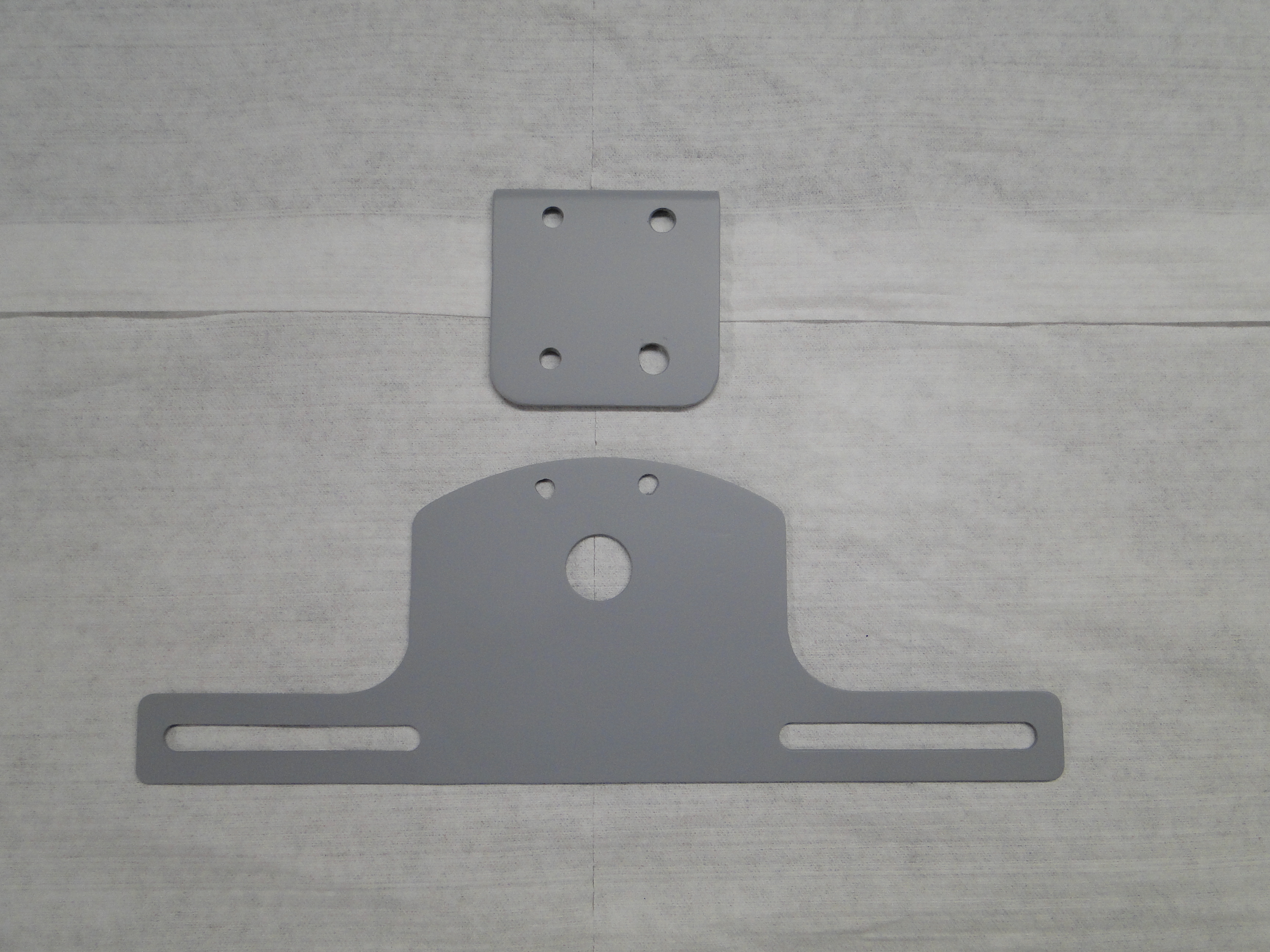
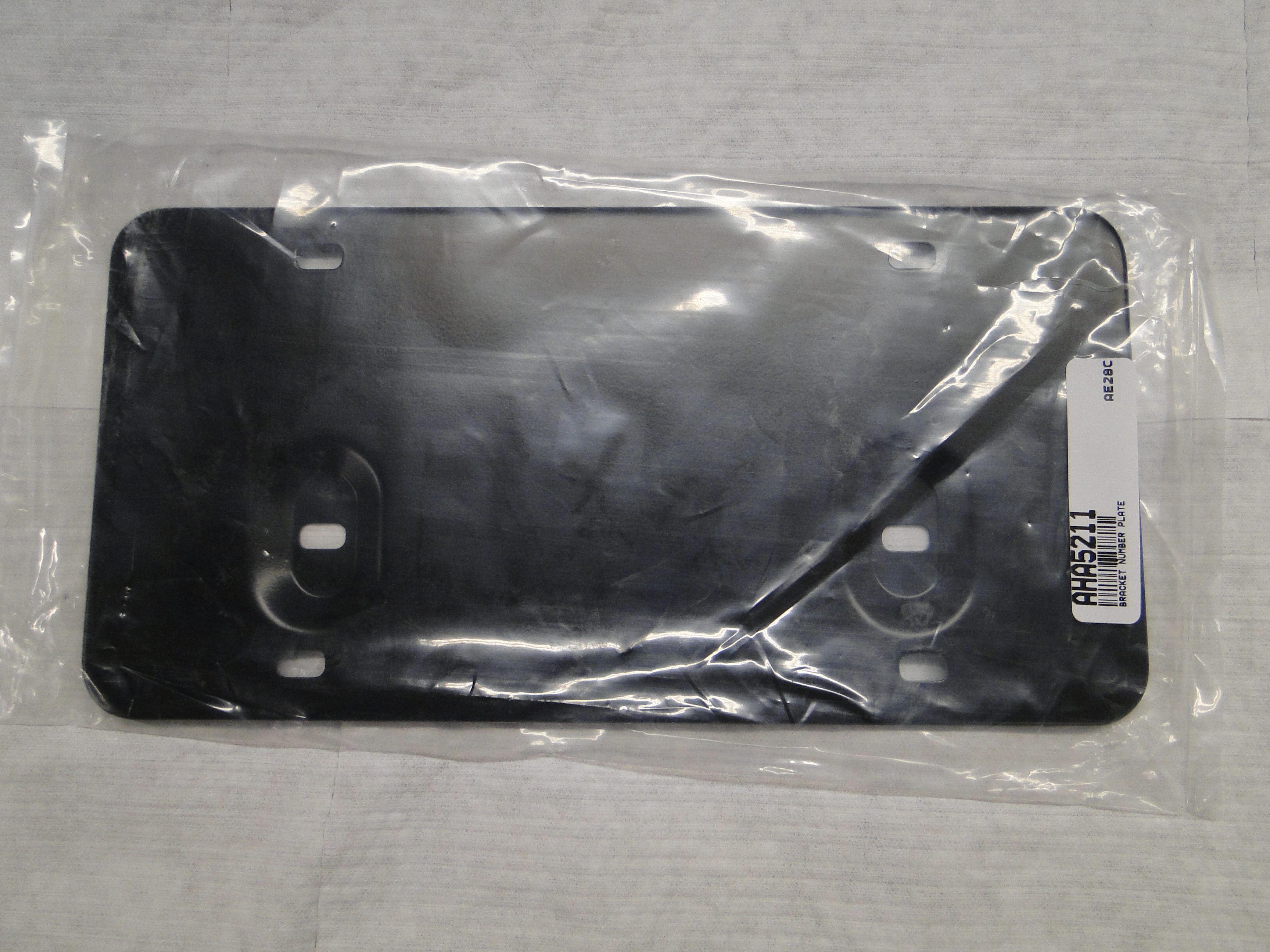
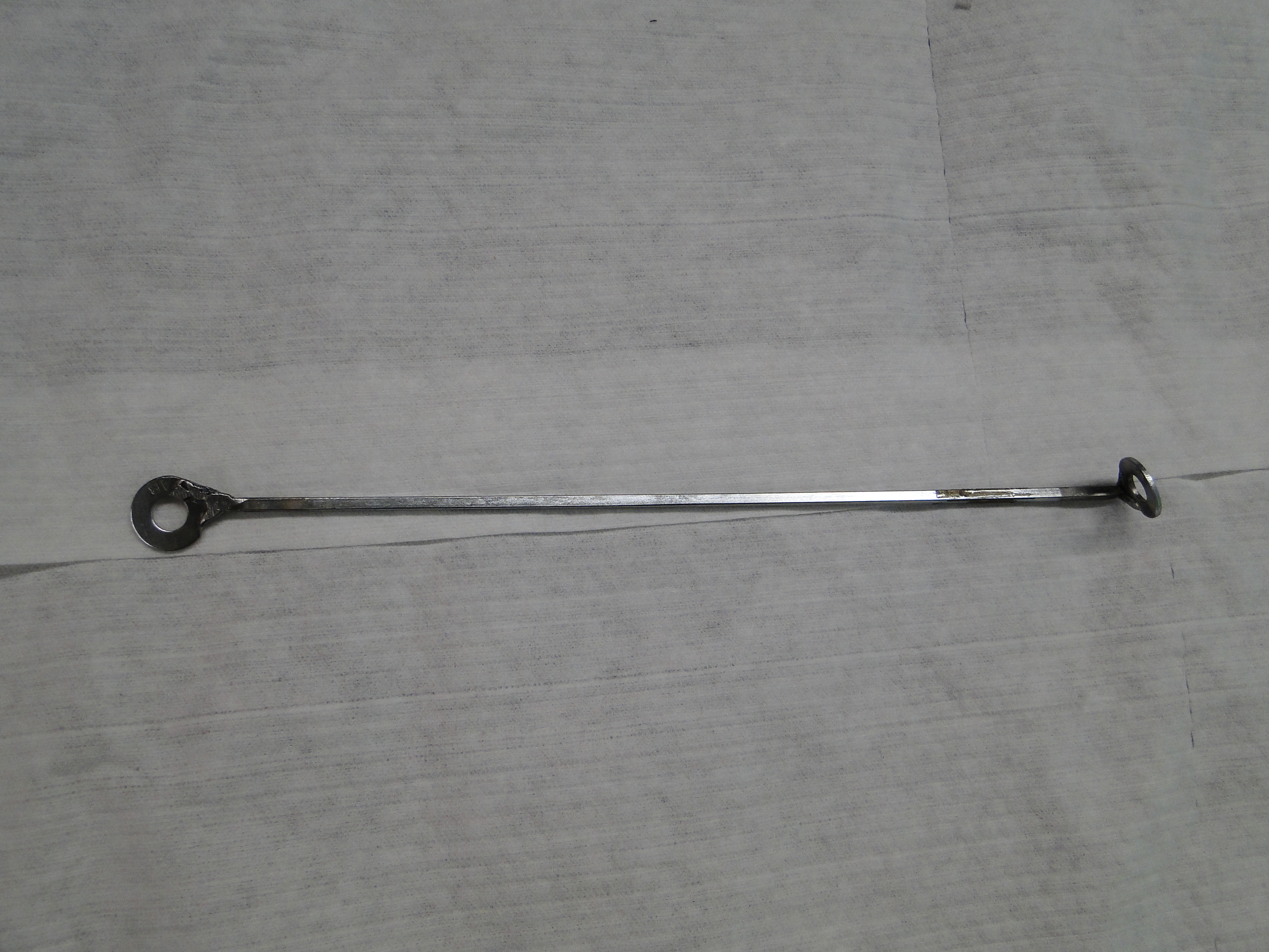
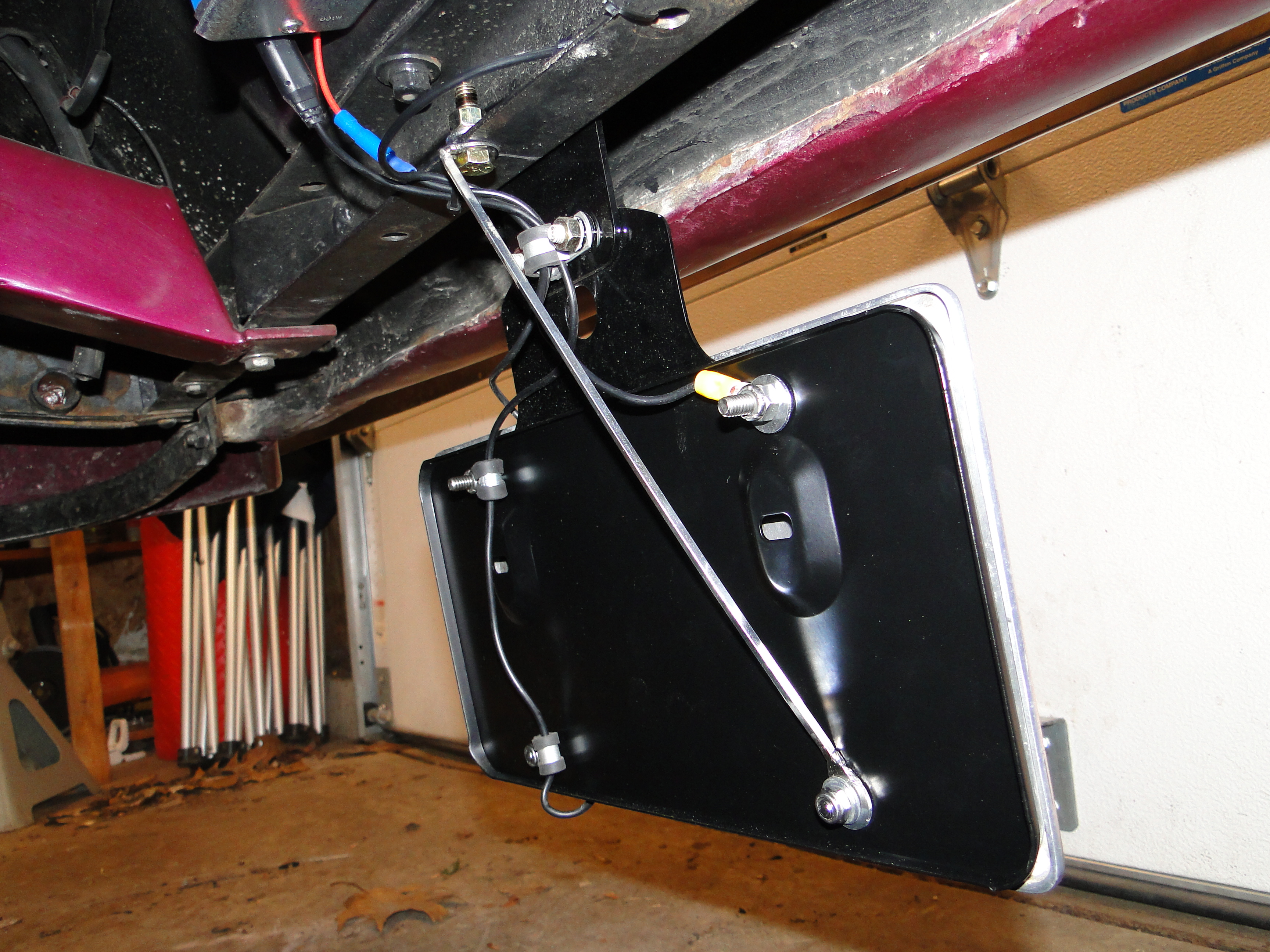
Camera And Monitor Installation Part 2
This is one of those theory and real life things. I made a bracket
for the license plate frame to mount the new camera to the car, however when I am driving down the
road. I noticed the camera is shaking from the back and forth. Now my plan is to
somehow reinforce the license plate frame with a
steel plate holder from a MGB that seems like it will do the job. I am going to
try and just mount everything from the license frame to the holder and hope I do
not have to do
anything more. When I attached the steel holder to the license plate
frame
it helped a lot but the camera was still moving. At this point I
thought maybe if I reinforced the bottom of the license plate it would stop
moving, so I fabricated a metal rod with a washer at each end for mounting.
Now we seem to be solid and have no movement.
Click any picture to enlarge.
Click any picture to enlarge.
August
Camera And Monitor Installation Part 3
The first time I used this system, If I don't say so my self, this
camera and monitor are way cool, wait not so fast for some reason the
monitor screen is lets just say grainy, real grainy and it also has wavy
lines in the picture to the point for me the system is unusable.
I was a little confused everything bench tested perfect, so I called
Tadi Brothers tech support and they told me I had a power problem
and to check the wires. I check the voltage and it was good,
I ran temporary wires from the battery and no change in monitor quality.
So I called Tati brothers tech support again, and now they said I had a
grounding problem. So I ran not one but two new ground
wires, one at the monitor end, one at the camera end, and no change to
the poor monitor quality. Yet again I called Tadi
Brothers tech support, they sent me a replacement monitor and I
replaced the monitor, still no change in poor monitor quality.
At this point I am becoming very frustrated so Tadi Brothers tech
support sent me a replacement camera and still no change in poor monitor
quality.
I was just about ready to send the whole camera and monitor kit back, when I talked to
Rodger at Tadi Brothers. He said something was interfering
with the camera signal, well now interference that is entirely different
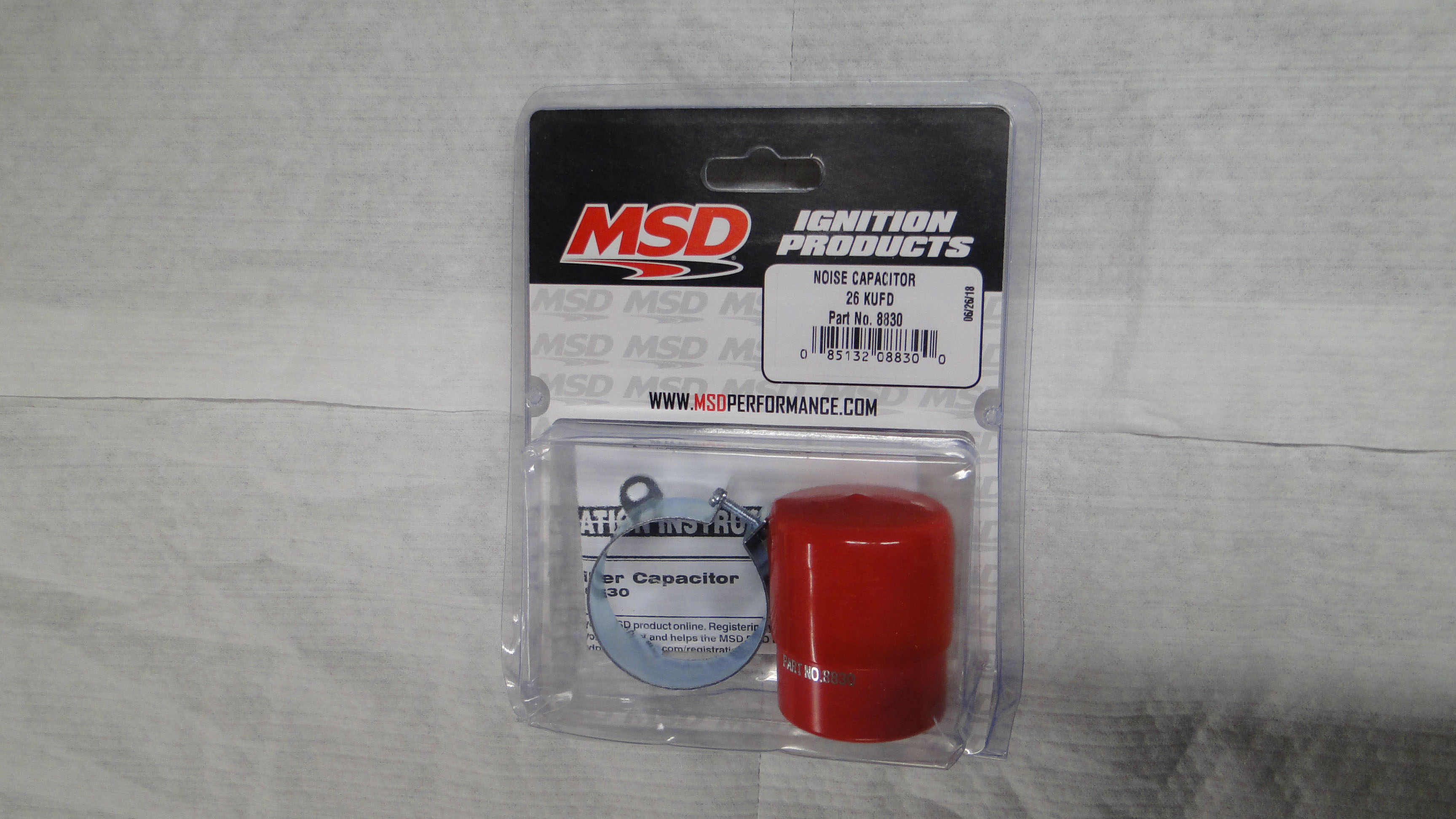
mater. My monster of a motor has an MSD electronic ignition,
so I purchased a line noise reducer from MSD, and my monitor screen
quality was much much better. But I was not happy just yet.
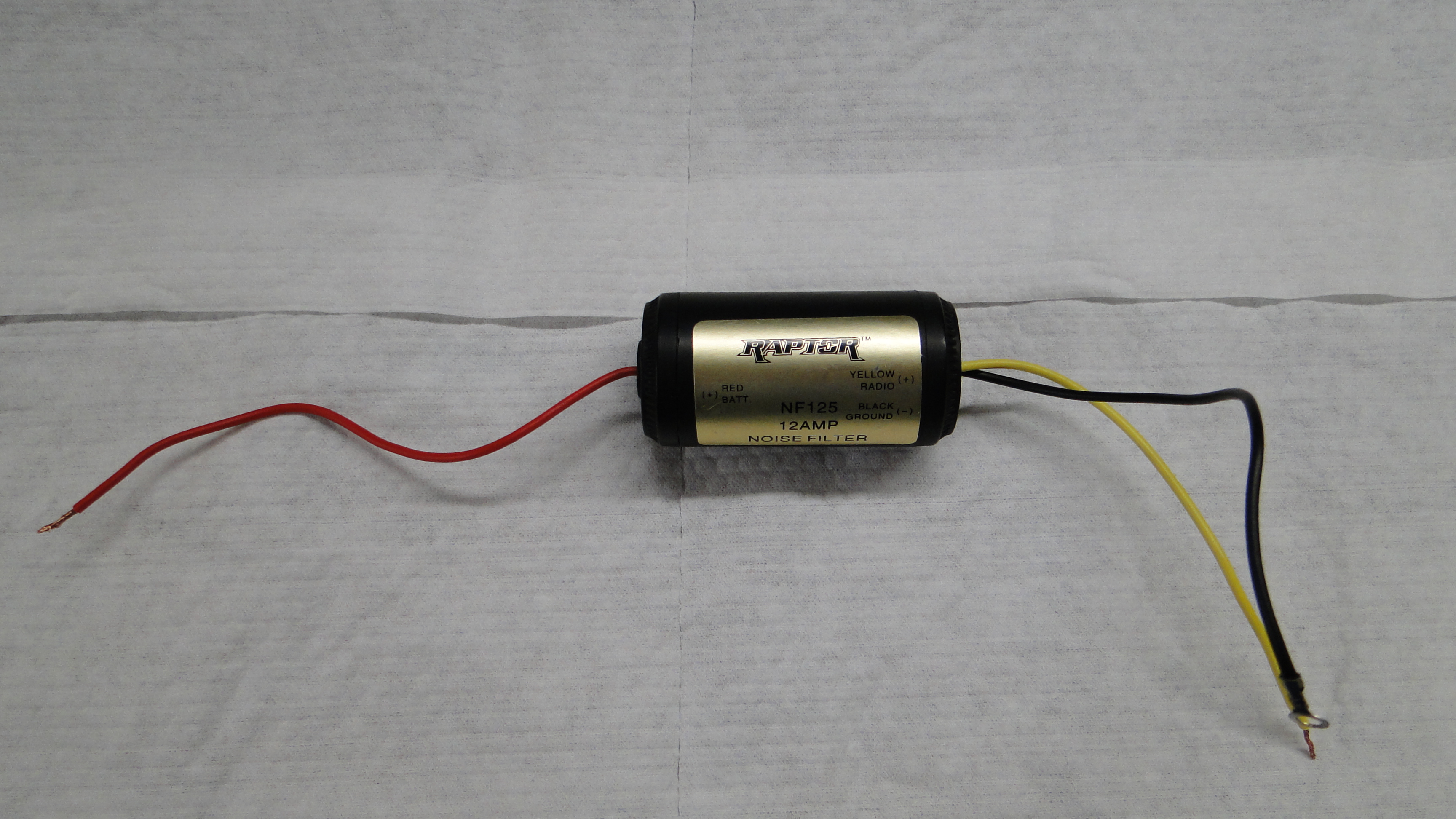
It could be even better I
thought, so I also purchased a Raptor noise filer, and with both
installed the monitor quality was right where it should be with no
interference.
Click any picture to enlarge.
October - November
Under Carriage Lighting
Ok so I had the Ford out for Ice cream one night, and a car pulled in
to the parking lot with lighting under the car that was
lighting up the road. I thought, that is really cool and I want
to do that to my Ford.
I did some R&D on the internet and
came up with the LED lights which were actually not expensive at all.
So I thought how hard could this be? Wow what a mistake that
was, this project turned out to be another nightmare from which I could
not wakeup from. I
have said it before, and I will say it again, nothing is easy with this
car.
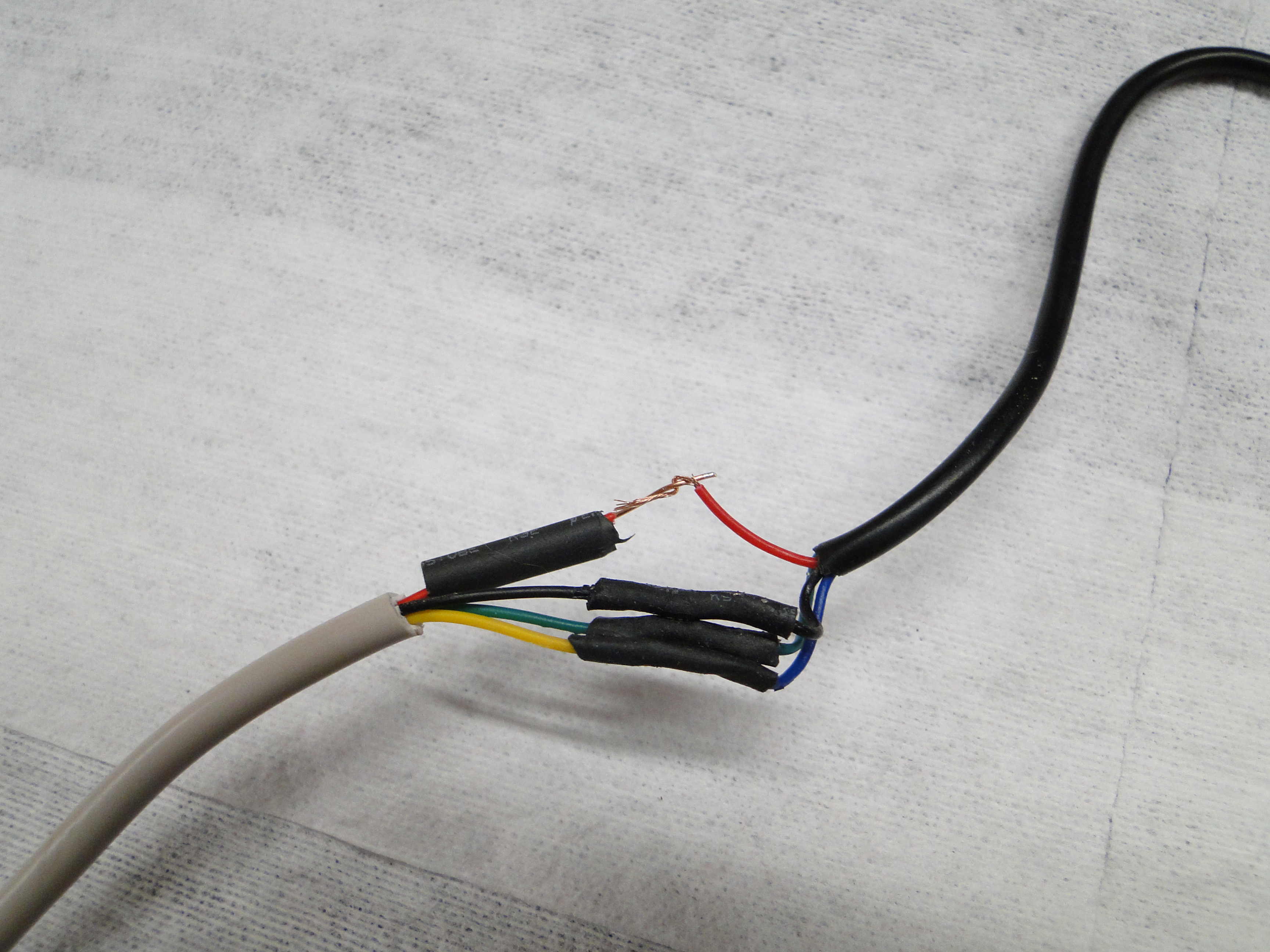
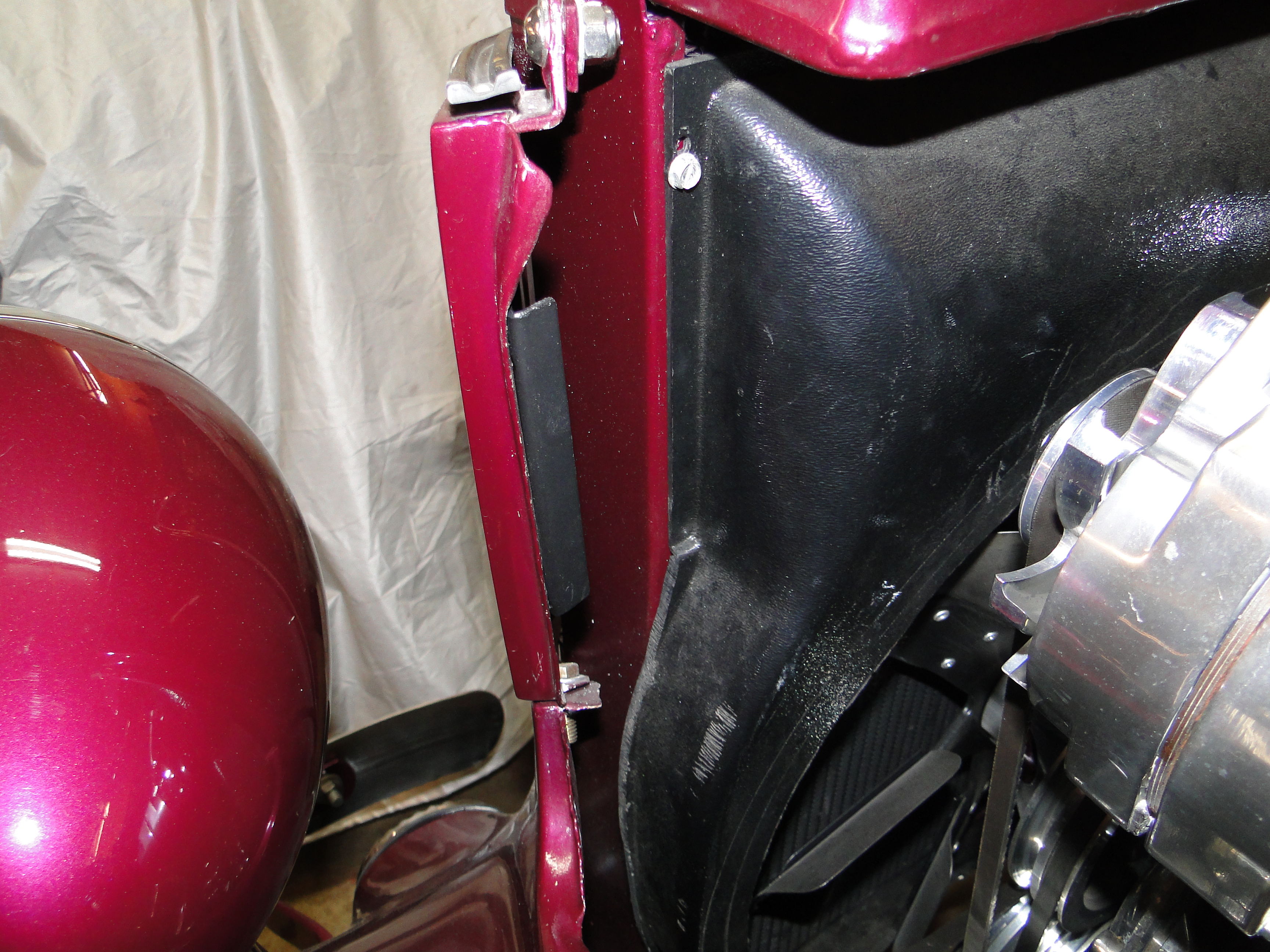
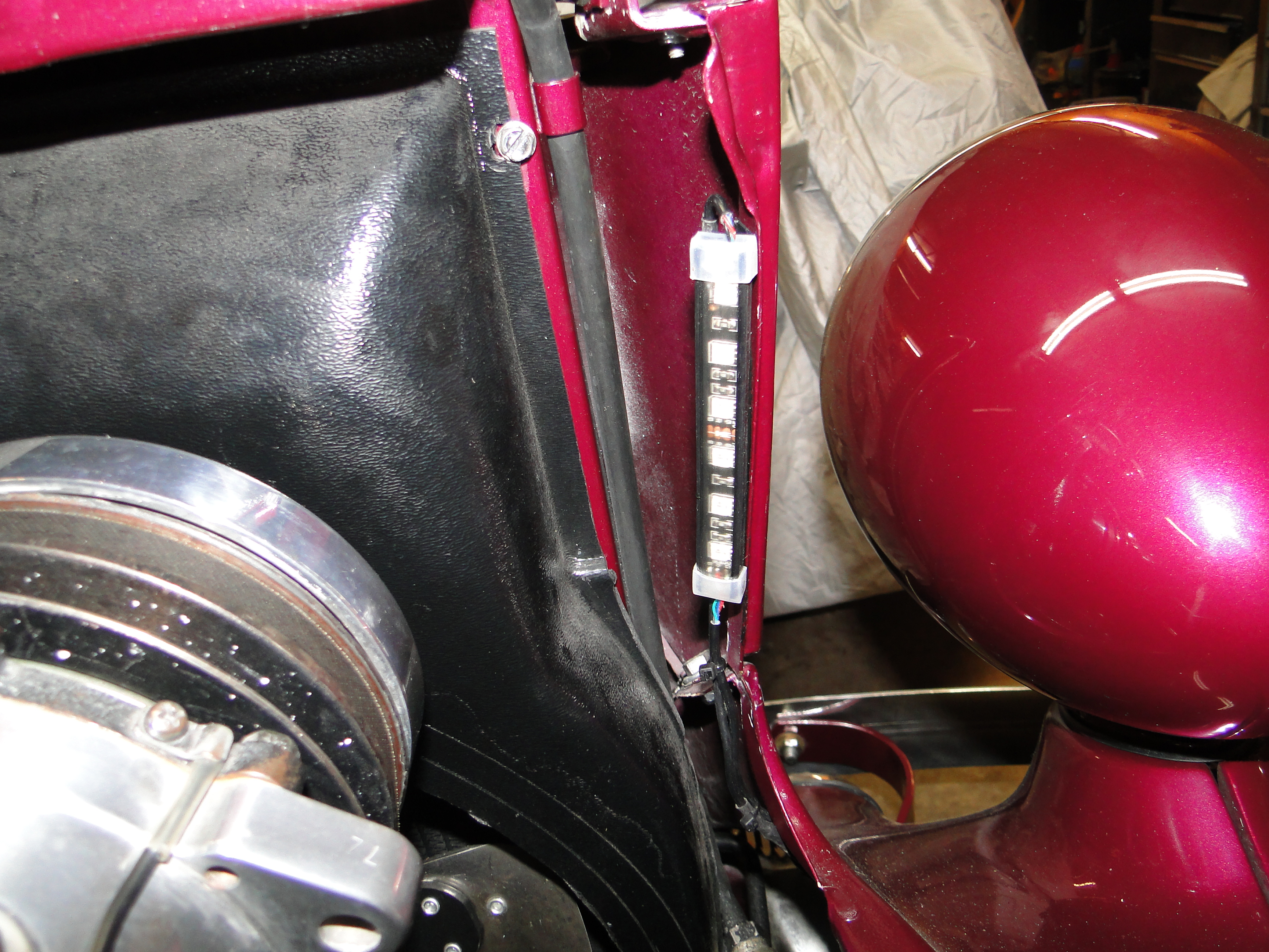
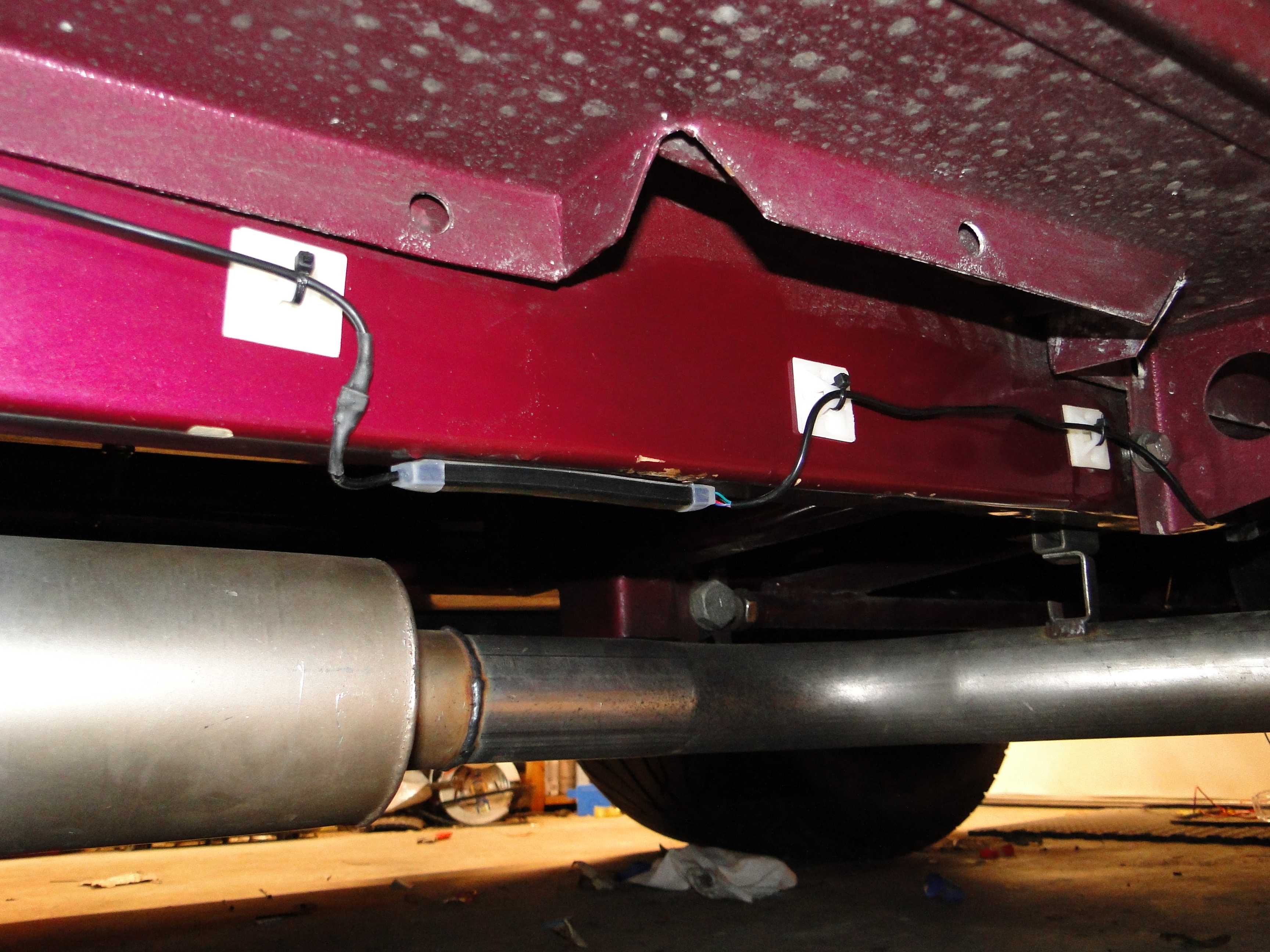
Between running the almost fifty feet of wire, soldering the 64 wire
connections for LED's, sealing
each connection with heat shrink tubes, testing and adjusting
the lights for balanced light distribution to prevent bright and dark spots under
the car, and
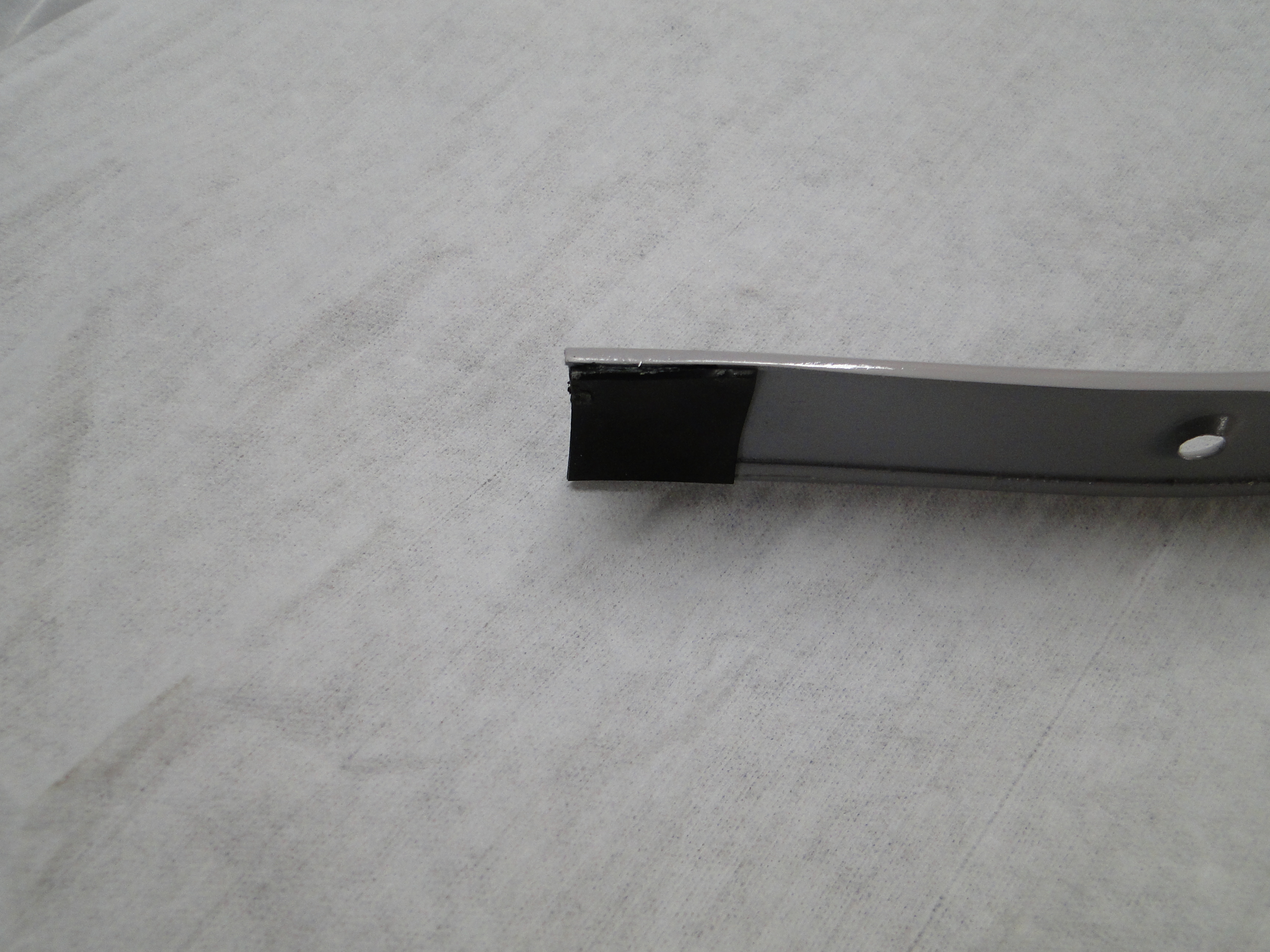
then mounting the LED lights to frame of the car. If that was not
bad enough, then in the engine compartment I
had to make metal brackets shown in black in the forth photo to mount the LED lights too. I averaged about two hours per LED
light installation time, and
I had 16 LED lights to install.
Then I had to synchronize
the controllers and mount them in a water tight location as well. This took what seem to be
forever to complete, however the lighting effects turned out way better then I
imagined.
Due to the in climate weather, I will have to wait until spring to get
any photos of the lighting effects on this website.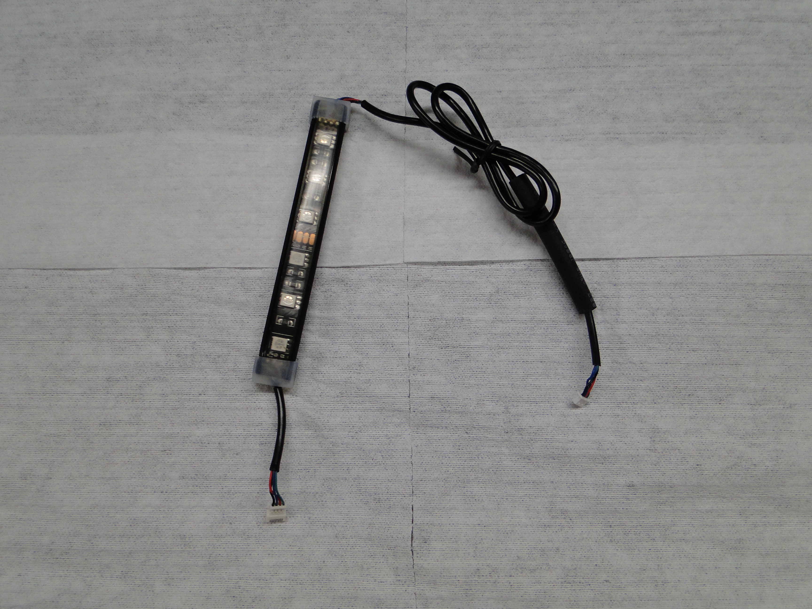


Click any picture to enlarge.
Contact Bob Capo at bob@bobcapo.com for further information
on any of our restorations.Thank You.